Telenetics 2185
In this application the main channel of 2185 A is connected to a host computer through a
Two subchannels are connected to 2185 B through two networks. One rout is through a digital network and the backup route is through a com- mon telephone network. Subchannels one and two of both 2185 A and 2185 B are set to DCE as that is the type of device to which they are connected. The main channel of 2185 B is set to DTE since it is con- nected to the controller. Clocking in this network is derived from the DSU connected to Subchannel One.
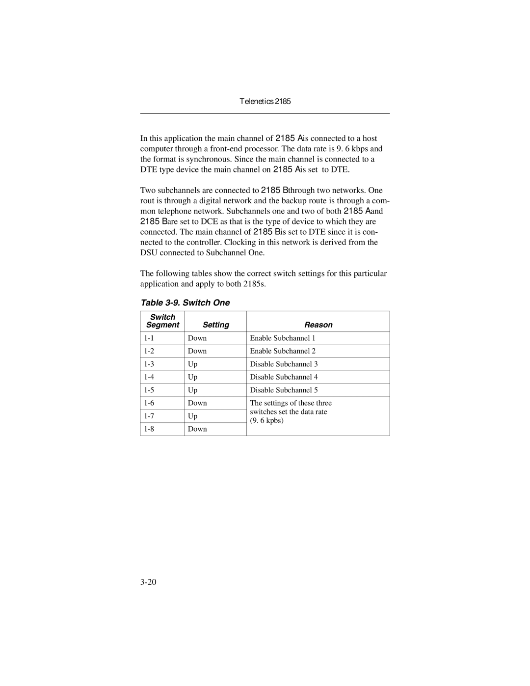
The following tables show the correct switch settings for this particular application and apply to both 2185s.
Table 3-9. Switch One
Switch |
|
| |
Segment | Setting | Reason | |
|
|
| |
Down | Enable Subchannel 1 | ||
|
|
| |
Down | Enable Subchannel 2 | ||
|
|
| |
Up | Disable Subchannel 3 | ||
|
|
| |
Up | Disable Subchannel 4 | ||
|
|
| |
Up | Disable Subchannel 5 | ||
|
|
| |
Down | The settings of these three | ||
|
| switches set the data rate | |
Up | |||
(9. 6 kpbs) | |||
|
| ||
Down |
| ||
|
|
|
