LOCAL HEADSET CONNECTION
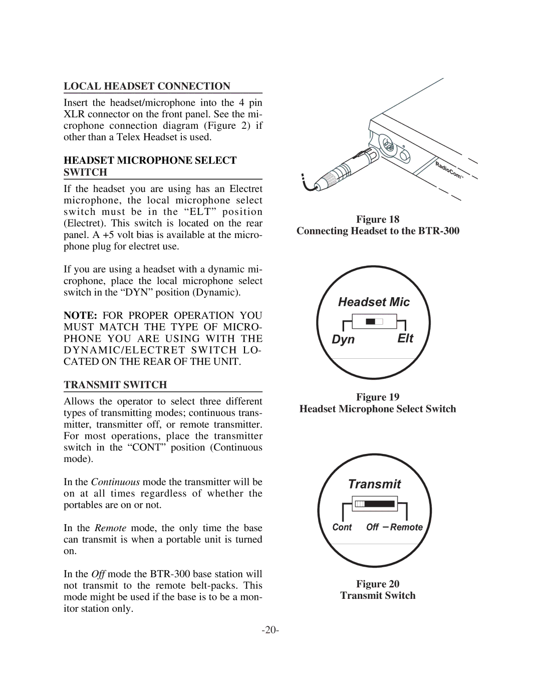
Insert the headset/microphone into the 4 pin XLR connector on the front panel. See the mi- crophone connection diagram (Figure 2) if other than a Telex Headset is used.
HEADSET MICROPHONE SELECT SWITCH
If the headset you are using has an Electret microphone, the local microphone select switch must be in the “ELT” position (Electret). This switch is located on the rear panel. A +5 volt bias is available at the micro- phone plug for electret use.
If you are using a headset with a dynamic mi- crophone, place the local microphone select switch in the “DYN” position (Dynamic).
NOTE: FOR PROPER OPERATION YOU MUST MATCH THE TYPE OF MICRO- PHONE YOU ARE USING WITH THE DYNAMIC/ELECTRET SWITCH LO- CATED ON THE REAR OF THE UNIT.
TRANSMIT SWITCH
Allows the operator to select three different types of transmitting modes; continuous trans- mitter, transmitter off, or remote transmitter. For most operations, place the transmitter switch in the “CONT” position (Continuous mode).
In the Continuous mode the transmitter will be on at all times regardless of whether the portables are on or not.
In the Remote mode, the only time the base can transmit is when a portable unit is turned on.
In the Off mode the
Figure 18
Connecting Headset to the
Headset Mic
Dyn Elt
Figure 19
Headset Microphone Select Switch
Transmit
Cont Off Remote
Figure 20
Transmit Switch