Transmit
Antenna
Auxiliary
Audio Output
PUSH |
|
|
| PUSH |
Auxiliary |
| Telex Communications Inc. Intercom | ||
Audio Input |
|
|
| Loop Thru |
|
|
| Transmit |
|
Headset Mic |
|
|
| |
Dyn | Elt | Cont | Off Remote | MADE IN U.S.A. |
Intercom
Receive
Antenna
| Power |
Volume |
|
Speaker | AC/DC 12V |
8 | 700 mA |
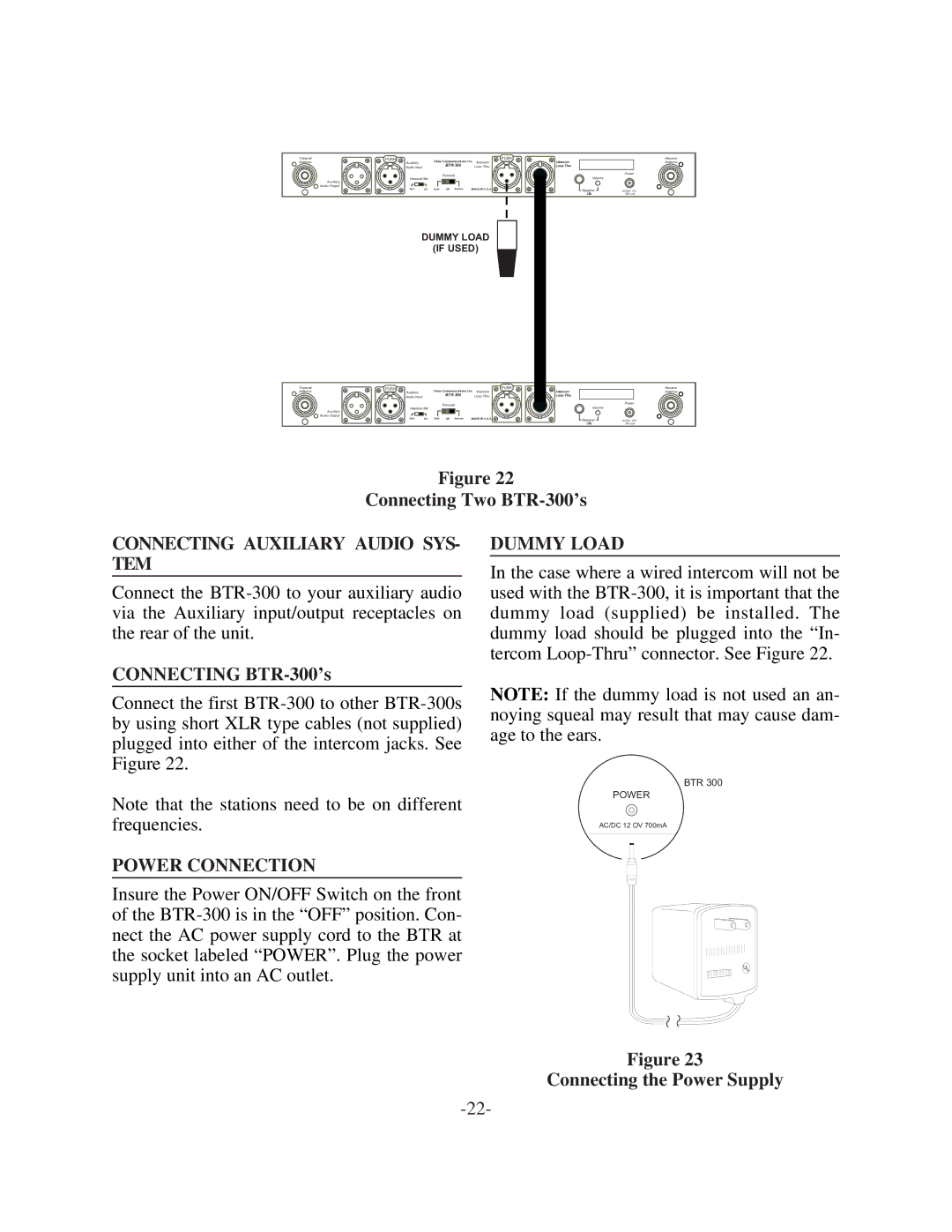
DUMMY LOAD
(IF USED)
Transmit
Antenna
Auxiliary
Audio Output
PUSH |
|
|
| PUSH |
Auxiliary |
| Telex Communications Inc. Intercom | ||
Audio Input |
|
| Loop Thru | |
|
|
| ||
|
|
| Transmit |
|
Headset Mic |
|
|
| |
Dyn | Elt | Cont | Off Remote | MADE IN U.S.A. |
Intercom
Receive
Antenna
| Power |
Volume |
|
Speaker | AC/DC 12V |
8 | 700 mA |
Figure 22
Connecting Two
CONNECTING AUXILIARY AUDIO SYS- TEM
Connect the
CONNECTING BTR-300’s
Connect the first
DUMMY LOAD
In the case where a wired intercom will not be used with the
NOTE: If the dummy load is not used an an- noying squeal may result that may cause dam- age to the ears.
Note that the stations need to be on different frequencies.
POWER CONNECTION
Insure the Power ON/OFF Switch on the front of the
BTR 300
POWER
AC/DC 12 OV 700mA
U![]()
Figure 23
Connecting the Power Supply