Board Layout
1.4 Board Layout
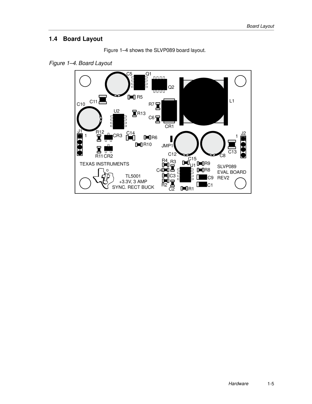
Figure 1–4 shows the SLVP089 board layout.
Figure 1–4. Board Layout
C5 Q1
![]() Q2
Q2
| C11 |
| R5 |
C10 |
| R7 | |
|
| U2 | R13 |
|
|
| |
|
|
| C6 |
CR1
L1
J1 | R12 | C14 |
|
|
| |
1 | CR3 |
|
|
| ||
|
| R6 |
|
|
| |
|
| R10 | JMP1 |
| ||
| R11 CR2 |
|
| C12 | C15 | |
|
| R4 |
| |||
TEXAS INSTRUMENTS | R3 | |||||
U1 | ||||||
|
| |||||
|
|
|
|
| ||
![]()
![]() R9
R9
1
C13
C8
SLVP089
J2
| C4 |
|
|
|
|
|
|
|
|
|
|
|
|
|
|
|
|
|
|
|
|
|
|
|
|
|
|
|
|
|
|
|
| ||
TL5001 |
|
|
| C3 |
|
|
|
|
|
|
|
|
|
| |||
|
|
|
|
|
|
|
|
|
|
|
| ||||||
|
|
|
|
|
|
|
|
|
|
|
| ||||||
|
|
|
|
|
|
|
|
|
| ||||||||
+3.3V, 3 AMP |
|
|
|
|
|
|
|
|
|
|
|
|
|
|
|
|
|
|
|
|
|
|
|
|
|
|
|
|
|
|
|
|
|
| |
|
|
|
|
|
|
|
|
|
|
|
|
|
|
|
|
| |
R2 |
|
|
|
|
|
|
|
|
|
|
|
| |||||
SYNC. RECT BUCK |
|
|
|
|
|
|
|
|
|
|
|
|
| R1 | |||
|
|
| C2 |
|
|
| |||||||||||
|
|
|
|
|
|
| |||||||||||
![]()
![]() R8 EVAL BOARD C9 REV2
R8 EVAL BOARD C9 REV2
![]() C1
C1
Hardware1-5