Introduction
1.1 Introduction
Synchronous buck converters provide the smaller size and higher efficiency required by electronic equipment, particularly portable battery-operated equipment. The synchronous buck converter reduces power losses associated with a standard buck converter by substituting a power MOSFET for the commutating diode. This reduces the typical 0.5-V to 1-V diode drop to 0.3 V or less and increases system efficiency by up to 10 percent. Continuous-current mode is desirable and is used in this EVM for the low peak-to-average current ratio. Figure 1–1 shows a typical synchronous buck converter.
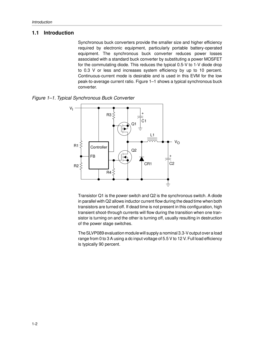
Figure 1–1. Typical Synchronous Buck Converter
VI
R1 
R2 
R3 
Controller
FB
R4 
Transistor Q1 is the power switch and Q2 is the synchronous switch. A diode in parallel with Q2 allows inductor current flow during the dead time when both transistors are turned off. If dead time is not present in this configuration, high transient shoot-through currents will flow during the transition when one tran- sistor is turning on and the other is turning off, usually resulting in destruction of the power stage switches.
The SLVP089 evaluation module will supply a nominal 3.3-V output over a load range from 0 to 3 A using a dc input voltage of 5.5 V to 12 V. Full load efficiency is typically 90 percent.