Input/Output Connections
1.3 Input/Output Connections
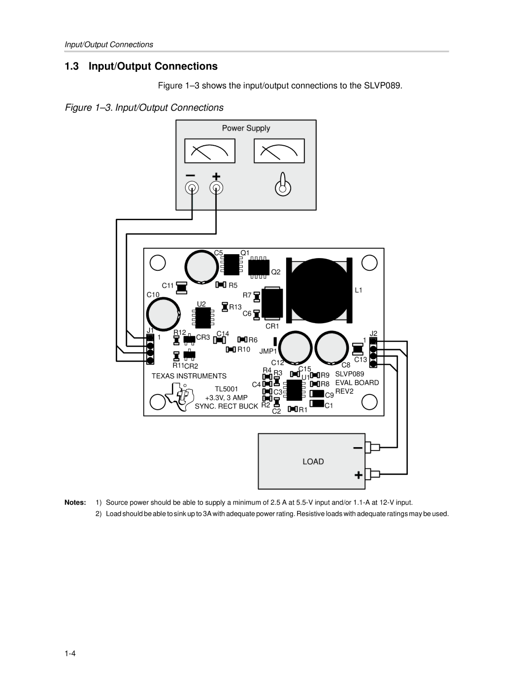
Figure 1–3 shows the input/output connections to the SLVP089.
Figure 1–3. Input/Output Connections
Power Supply
– +
|
|
| C5 | Q1 |
|
|
|
|
|
|
|
|
|
|
| Q2 |
|
|
|
| C11 |
|
| R5 |
|
|
|
| L1 |
C10 |
|
|
| R7 |
|
|
|
| |
|
|
|
|
|
|
|
| ||
|
| U2 |
| R13 |
|
|
|
|
|
|
|
|
|
|
|
|
|
| |
|
|
|
| C6 |
|
|
|
|
|
J1 | R12 |
| C14 |
| CR1 |
|
| J2 | |
|
|
|
|
| |||||
1 | CR3 |
|
|
|
| ||||
|
|
|
|
| |||||
|
|
|
| R6 |
|
|
| 1 | |
|
|
|
| R10 | JMP1 |
|
|
| |
|
|
|
|
|
| C12 |
|
| C13 |
| R11CR2 |
|
|
| C15 |
| C8 | ||
|
|
|
| R4 R3 |
| ||||
TEXAS INSTRUMENTS |
|
| R9 | SLVP089 | |||||
|
| U1 | |||||||
|
|
| TL5001 | C4 |
|
| R8 | EVAL BOARD | |
|
|
|
| C3 |
| C9 REV2 | |||
|
| +3.3V, 3 AMP |
|
| |||||
|
|
| R2 |
| C1 |
| |||
|
| SYNC. RECT BUCK | R1 |
| |||||
|
|
|
|
|
| C2 |
|
| |
– ![]()
![]()
LOAD
+ ![]()
![]()
Notes: 1) Source power should be able to supply a minimum of 2.5 A at
2) Load should be able to sink up to 3A with adequate power rating. Resistive loads with adequate ratings may be used.