SWRA004A
Low-Band Cascaded: 1dB RF Input Compression Point
Control state: 011000
SEE APPENDIX A: TEST BENCH SETUPS
Test setup Figure 20
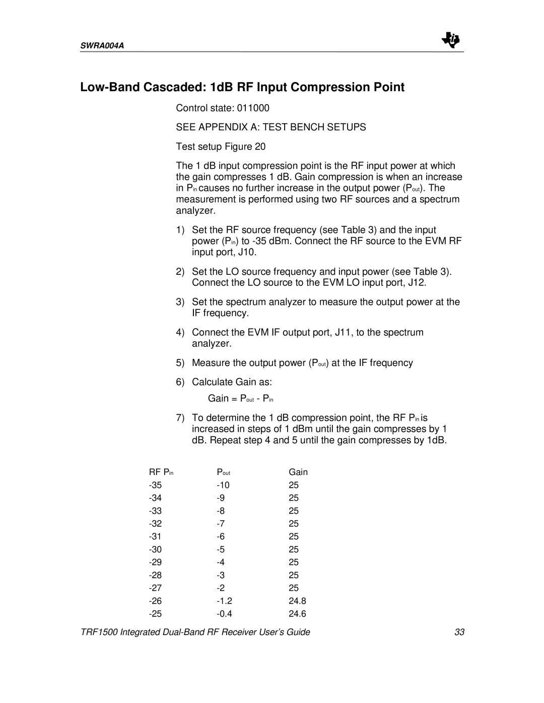
The 1 dB input compression point is the RF input power at which the gain compresses 1 dB. Gain compression is when an increase in Pin causes no further increase in the output power (Pout). The measurement is performed using two RF sources and a spectrum analyzer.
1)Set the RF source frequency (see Table 3) and the input power (Pin) to
2)Set the LO source frequency and input power (see Table 3). Connect the LO source to the EVM LO input port, J12.
3)Set the spectrum analyzer to measure the output power at the IF frequency.
4)Connect the EVM IF output port, J11, to the spectrum analyzer.
5)Measure the output power (Pout) at the IF frequency
6)Calculate Gain as:
Gain = Pout - Pin
7)To determine the 1 dB compression point, the RF Pin is increased in steps of 1 dBm until the gain compresses by 1 dB. Repeat step 4 and 5 until the gain compresses by 1dB.
RF Pin | Pout | Gain |
|
25 |
| ||
25 |
| ||
25 |
| ||
25 |
| ||
25 |
| ||
25 |
| ||
25 |
| ||
25 |
| ||
25 |
| ||
24.8 |
| ||
24.6 |
| ||
TRF1500 Integrated | 33 | ||