SWRA004A
Figure 5. Low-Band LNA Output Configuration
Surface Acoustic Wave (SAW) Filter
The SAW filter is used primarily as an image-reject filter (IRF). The image frequency (fIM) is located at the desired channel frequency (fCH) plus two times the IF frequency (fIF); fIM = fCH + (2 x fIF). The image frequency acts as an interferer to the system. During the down-conversion process, the image and the desired channel are both converted to a common IF. Left unfiltered, the image could completely mask the desired signal. The IRF rejects this image before the RF signal is introduced to the mixer.
By minimizing the image before it reaches the mixer, the sensitivity of the receiver is enhanced. To further minimize potential interferers, a band-select filter is typically used at the front of the receiver, before the LNA. The band-select filter passes only those frequencies that fall within the system receive band. In many TDMA systems, the duplexor acts as the band-select filter.
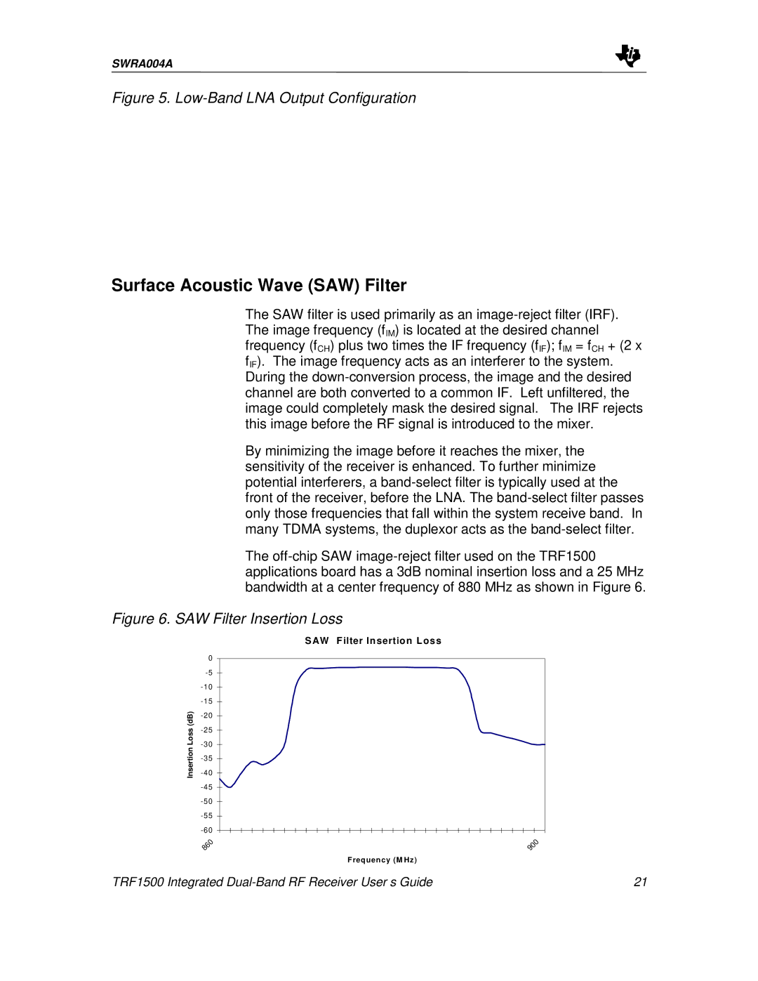
The off-chip SAW image-reject filter used on the TRF1500 applications board has a 3dB nominal insertion loss and a 25 MHz bandwidth at a center frequency of 880 MHz as shown in Figure 6.
Figure 6. SAW Filter Insertion Loss
S AW F ilter In sertio n L oss
| 0 | |
| -5 | |
| -10 | |
| -15 | |
(dB) | -20 | |
-25 | |
Loss | |
-30 | |
Insertion | |
-35 | |
-40 | |
| |
| -45 | |
| -50 | |
| -55 | |
| -60 | |
| 860 | 900 |
| | F req uen cy (M Hz) |
TRF1500 Integrated Dual-Band RF Receiver User’s Guide | 21 |