SWRA004A
Low-Band LNA Stand-Alone Test Guide
This section involves measuring the Low Band LNA by itself. All unused ports are terminated into 50Ω. Before measuring the low band LNA by itself the EVM board must be modified as follows: Remove C12 and place C53. The EVM board is now modified to use J15 as the output port of the LNA.
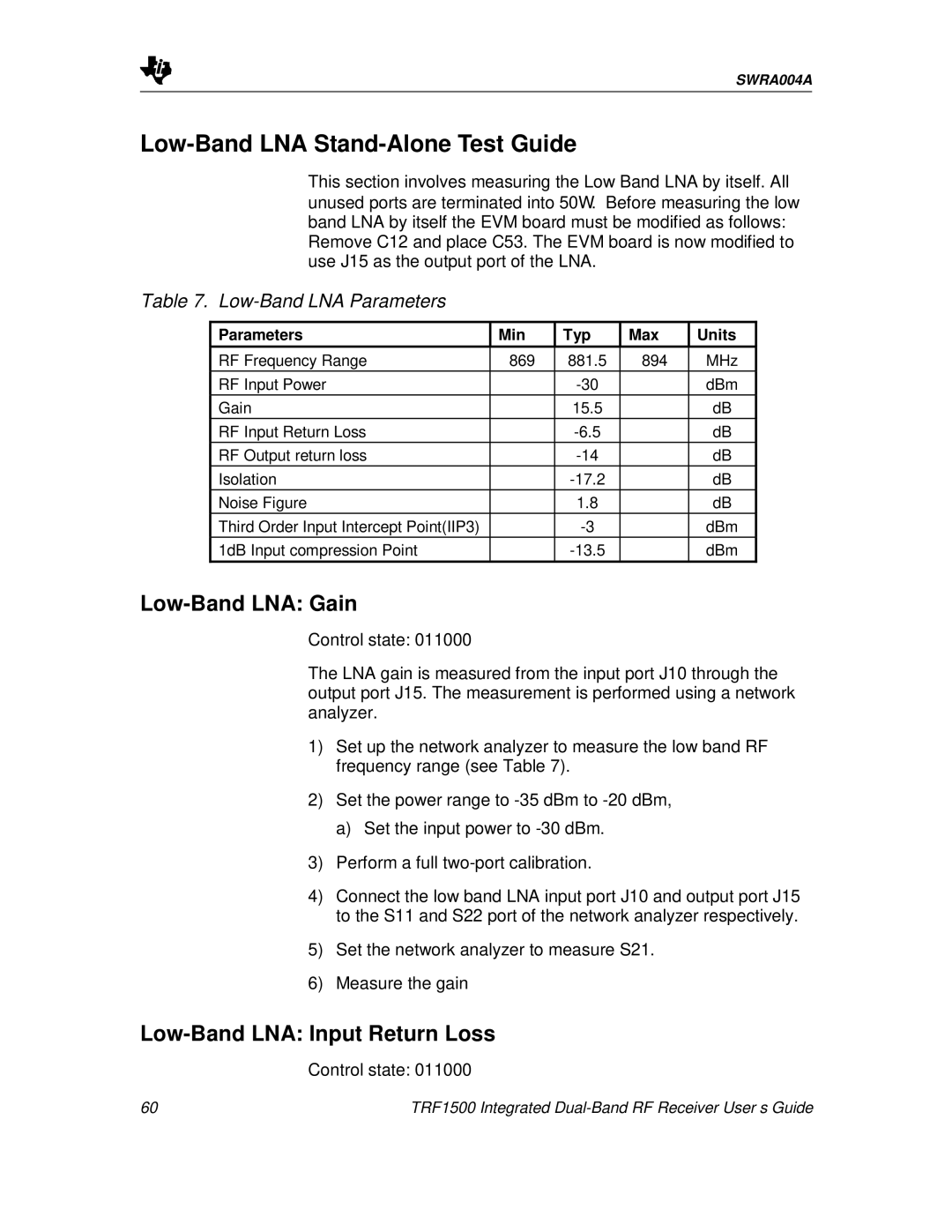
Table 7. Low-Band LNA Parameters
Parameters | Min | Typ | Max | Units |
|
|
|
|
|
RF Frequency Range | 869 | 881.5 | 894 | MHz |
RF Input Power |
|
| dBm | |
Gain |
| 15.5 |
| dB |
RF Input Return Loss |
|
| dB | |
RF Output return loss |
|
| dB | |
Isolation |
|
| dB | |
Noise Figure |
| 1.8 |
| dB |
Third Order Input Intercept Point(IIP3) |
|
| dBm | |
1dB Input compression Point |
|
| dBm |
Low-Band LNA: Gain
Control state: 011000
The LNA gain is measured from the input port J10 through the output port J15. The measurement is performed using a network analyzer.
1)Set up the network analyzer to measure the low band RF frequency range (see Table 7).
2)Set the power range to
a)Set the input power to
3)Perform a full
4)Connect the low band LNA input port J10 and output port J15 to the S11 and S22 port of the network analyzer respectively.
5)Set the network analyzer to measure S21.
6)Measure the gain
Low-Band LNA: Input Return Loss
Control state: 011000
60 | TRF1500 Integrated |