SWRA004A
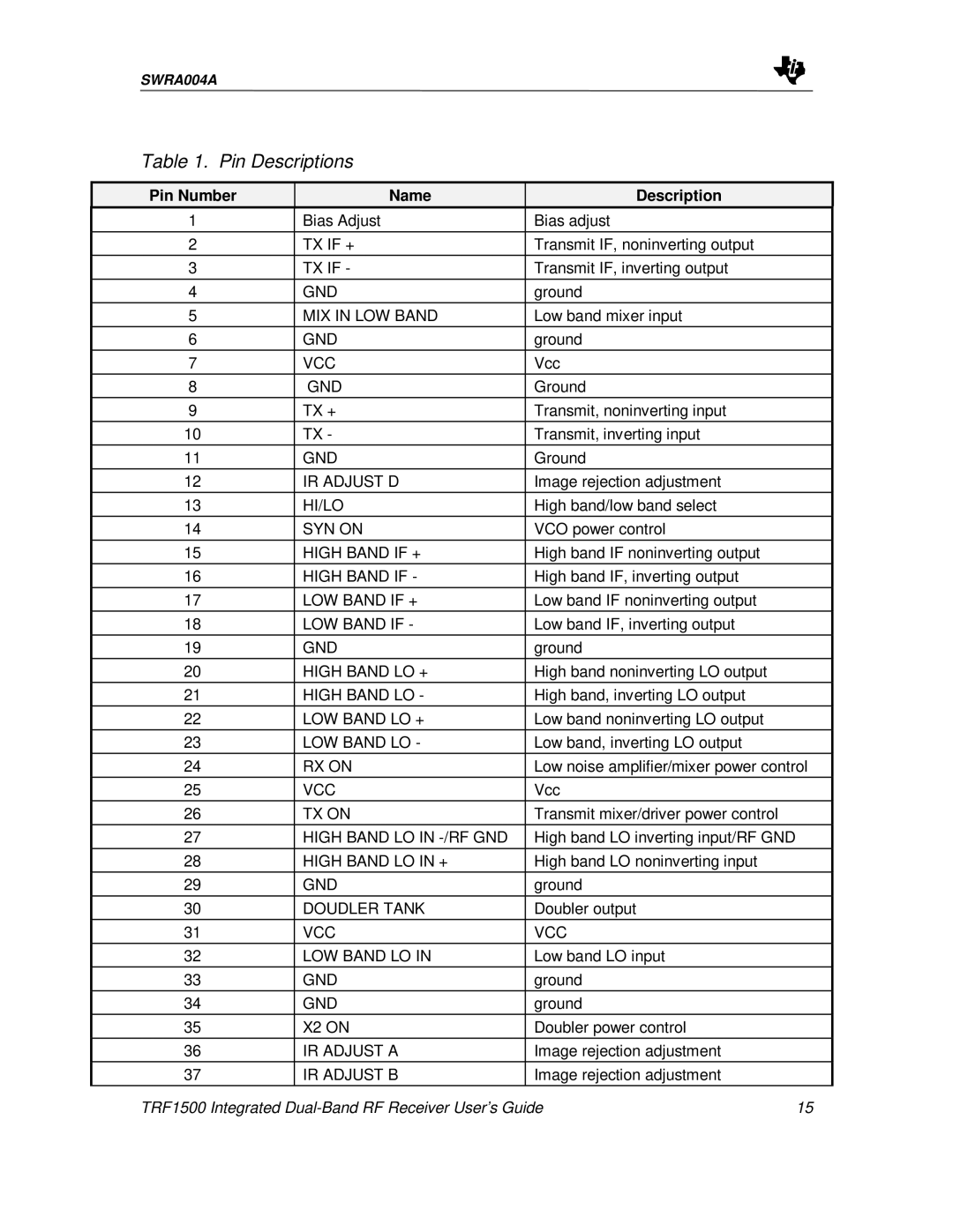
Table 1. Pin Descriptions
Pin Number | Name | Description |
|
1 | Bias Adjust | Bias adjust |
|
2 | TX IF + | Transmit IF, noninverting output |
|
3 | TX IF - | Transmit IF, inverting output |
|
|
|
|
|
4 | GND | ground |
|
5 | MIX IN LOW BAND | Low band mixer input |
|
6 | GND | ground |
|
7 | VCC | Vcc |
|
8 | GND | Ground |
|
9 | TX + | Transmit, noninverting input |
|
10 | TX - | Transmit, inverting input |
|
11 | GND | Ground |
|
12 | IR ADJUST D | Image rejection adjustment |
|
13 | HI/LO | High band/low band select |
|
14 | SYN ON | VCO power control |
|
|
|
|
|
15 | HIGH BAND IF + | High band IF noninverting output |
|
16 | HIGH BAND IF - | High band IF, inverting output |
|
17 | LOW BAND IF + | Low band IF noninverting output |
|
18 | LOW BAND IF - | Low band IF, inverting output |
|
19 | GND | ground |
|
20 | HIGH BAND LO + | High band noninverting LO output |
|
21 | HIGH BAND LO - | High band, inverting LO output |
|
22 | LOW BAND LO + | Low band noninverting LO output |
|
23 | LOW BAND LO - | Low band, inverting LO output |
|
24 | RX ON | Low noise amplifier/mixer power control | |
25 | VCC | Vcc |
|
26 | TX ON | Transmit mixer/driver power control |
|
27 | HIGH BAND LO IN | High band LO inverting input/RF GND |
|
|
|
|
|
28 | HIGH BAND LO IN + | High band LO noninverting input |
|
29 | GND | ground |
|
30 | DOUDLER TANK | Doubler output |
|
31 | VCC | VCC |
|
32 | LOW BAND LO IN | Low band LO input |
|
33 | GND | ground |
|
34 | GND | ground |
|
35 | X2 ON | Doubler power control |
|
36 | IR ADJUST A | Image rejection adjustment |
|
37 | IR ADJUST B | Image rejection adjustment |
|
TRF1500 Integrated | 15 | ||