OL6RX072DV5R
OL6RA072D48B/R
OL6FA072D48B/R
OL6RA072DV5B/R
CONTENTS
Fuel
Configuration
Feature
Model Number Digit
1.Excess oil has accumulated
I. SAFETY SECTION
cWARNING AND CAUTIONS
cCAUTION DO NOT ATTEMPT TO START THE BURNER WHEN
Page
a. Combustible material
A. CODES AND CLEARANCES
b. Non-combustiblematerial
MODEL NO
A. CHIMNEY
TYPE OF
FROM
2. PREVENTION OF CHIMNEY CONDENSING
1. PROPER CHIMNEY SIZE
3. PROPER CHIMNEY HEIGHT
4. PROPER VENT CONNECTOR PIPE/CHIMNEY CONNECTION
9 FLUE PIPE CLEARANCES, SIZING AND TYPE
7. TIGHT CLEAN-OUTDOORS AND CONNECTIONS
6. TIGHT JOINTS
8. NO INTERCONNECTED CHIMNEY FLUES
B. VENTING
C. DRAFT REGULATORS
ROTATION OF FRONT FLUE ELBOW
Note Do not use with Direct Vent application
Airflow Requirements and Sizing of Duct Work
D. DUCT WORK/AIR CONDITIONING
Page
The ASHRAE Handbook - Fundamentalsis an excellent source of duct system design principles and pressure drop data. Conversely, for a specified type of fitting, it is also possible to determine the required size or diameter of the component for a specified pressure drop and flow rate
1.1 X TR TEMPERATURE RISE, F = HEATINGCFM
1.HEATING CFM HEAT OUTPUT OF FURNACE BTUH
Filter Type
E. Air Filters Mounted Internal to Furnace
Maximum
Model Number
F. LIMIT POSITION AND LOCATION
DO NOT CHANGE POSITION OF THE CHAMBER
G. BURNER INSTALLATION
NOZZLE SIZE
H. BURNER SPECIFICATIONS AND APPLICATIONS
OIL NOZZLE CAPACITY CHART
+ INSULATOR S = SLEEVE OR N = NONE
NOZZLE SIZE
2 STAGE FIRING RATES
CAPACITY
FIRING
I. OIL TANK AND PIPING
MOUNTING THE 2-STAGERIELLO BURNER
5.A readily accessible, design-certified,manual oil shutoff valve, with a non-displaceablerotor member, shall be installed in the fuel oil supply piping within 6 feet of the appliance
Maximum
J. OIL FILTER
K. ELECTRICAL WIRIING
Assembly
Wire size selections in Table 10 are based upon Table 310-16of the National Electrical Codefor three copper conductors, with insulation rated for 75 degrees Celsius, contained in raceway at 30 degrees Celsius. For other wire insulation temperature ratings and ambient conditions, refer to the National Electrical Codefor the minimum wire sizing requirements
Thermostat Anticipator Setting
Preferred method of adjustment
L. Blower Motor Speed Selection
Draw Amps/ / Watts vs
Heating Speed Set-ups
OL6*A072DV5
Furnace Motor Current
Heating Speed Set-ups 2 - Stage OL6*X072DV5
LOW CAPACITY
HIGH CAPACITY
= Recommended heating speed setting
External Static Pressure in W.C
Cooling Speed Set-ups OL6**072DV5
Furnace Motor Current
Draw Amps / Watts vs
Page
TERMINAL DEFINITIONS & FIELD WIRING
M. BLOWER CONTROLLER INFORMATION FOR PSC MOTOR
B. Outputs
A. Inputs
C. Operating Modes
Heat Mode
DIAGNOSTIC FEATURES
PSC TROUBLE SHOOTING
i.STOP! Read the safety information above
N. STARTUP PROCEDURES
Operating Instructions
For Your Safety Read Before Operating
To Turn Off Oil to Appliance
2. Adjustment of Burner Combustion
COMBUSTION HEAD SETTING FOR 2-STAGERIELLO BURNER
TURN TO THE RIGHT SIGN +
AIR DAMPER ADJUSTMENT
TURN TO THE LEFT SIGN
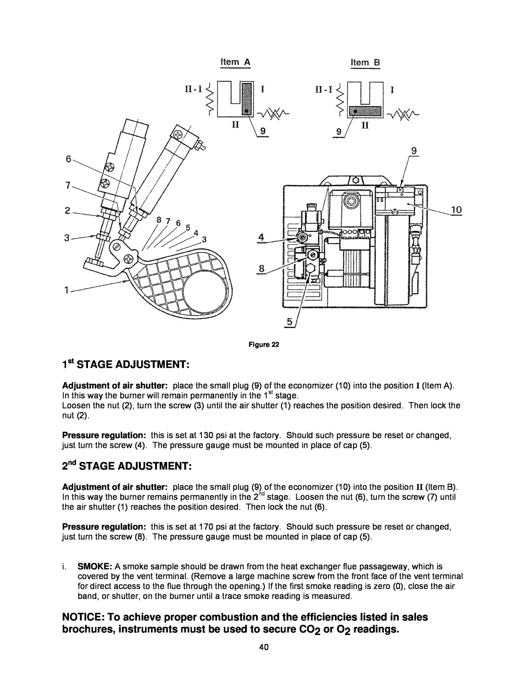
2nd STAGE ADJUSTMENT
1st STAGE ADJUSTMENT
Notice Minimum return air temperature is 55F
3. Adjustment Of Heat Input Rate
4. Setting Supply Air Temperature Rise
5. Checkout Procedure
cCAUTION DO NOT ATTEMPT TO START THE BURNER WHEN
III. USERS INFORMATION SECTION
C. INSPECTION AREAS
cCAUTION DO NOT ATTEMPT TO MAKE REPAIRS YOURSELF
D. STARTING THE BURNER
E. FILTER CLEANING AND LOCATION
IV. INSTALLERS INSTRUCTIONS TO USER
A.GENERAL INSPECTION
V. DEALER MAINTENANCE
SAFETY DURING SERVICING AND INSPECTION
B. HEAT EXCHANGER
C. HEAT EXCHANGER CLEANING INSTRUCTIONS
Vacuum Hose Length OL6 8FT
Figure 24 Heat Exchanger Clean-Outs
F. SUPPLY/RETURN AIR FILTER
Filter maintenance procedure
D. ELECTRICAL SYSTEM
E. SUPPLY/RETURN AIR BLOWER
G. EXTENDED APPLIANCE SHUTDOWN
Filter replacement
ON STARTUP
2.Remove the furnace front door
Riello Burner
Beckett Burner
PERSONNEL, AND NOT BY THE FURNACE OWNER
VII. TROUBLESHOOTING
A. DIAGNOSTICS
Diagnostic Features
B. CAD CELL CHECKOUT PROCEDURE
VIII. Sequence of Operations Flow Chart
Page
IX. Trouble Shooting Flow Chart
Page
Page
Page
Page
HEATING
CUSTOMER
SYSTEM
Replacement Parts for OL6F*072D
Appendix - A Replacement Parts
Page
Replacement Parts for OL6R*072D
Page
OL6*A072D48 PSC Wiring Diagram
Appendix - B Wiring Diagrams
OL6*A072DV5 ECM Wiring Diagram
OL6*X072DV5 ECM 2-StageWiring Diagram