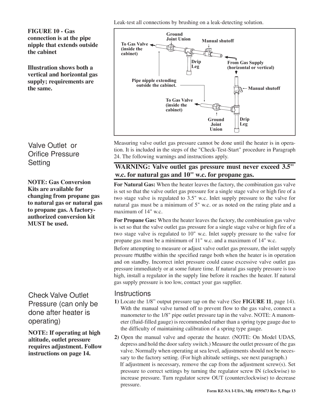
FIGURE 10 - Gas connection is at the pipe nipple that extends outside the cabinet

Illustration shows both a vertical and horizontal gas supply; requirements are the same.

Valve Outlet or

Orifice Pressure

Setting

NOTE: Gas Conversion Kits are available for changing from propane gas to natural gas or natural gas to propane gas. A factory- authorized conversion kit MUST be used.

Check Valve Outlet Pressure (can only be done after heater is operating)

NOTE: If operating at high altitude, outlet pressure requires adjustment. Follow instructions on page 14.

Leak-test all connections by brushing on a leak-detecting solution.

Ground


Joint Union

Manual shutoff

To Gas Valve


(inside the


cabinet)


Drip


From Gas Supply

Leg


(horizontal or vertical)

Pipe nipple extending


outside the cabinet.


Manual shutoff


To Gas Valve


(inside the


cabinet)


Ground

Drip


Joint

Leg


Union


Measuring valve outlet gas pressure cannot be done until the heater is in opera- tion. It is included in the steps of the "Check-Test-Start" procedure in Paragraph 24. The following warnings and instructions apply.

WARNING: Valve outlet gas pressure must never exceed 3.5" w.c. for natural gas and 10" w.c. for propane gas.

For Natural Gas: When the heater leaves the factory, the combination gas valve is set so that the valve outlet gas pressure for a single stage valve or high fire of a two stage valve is regulated to 3.5" w.c. Inlet supply pressure to the valve for natural gas must be a minimum of 5" w.c. or as noted on the rating plate and a maximum of 14" w.c.

For Propane Gas: When the heater leaves the factory, the combination gas valve is set so that the valve outlet gas pressure for a single stage valve or high fire of a two stage valve is regulated to 10" w.c. Inlet supply pressure to the valve for propane gas must be a minimum of 11" w.c. and a maximum of 14" w.c.

Before attempting to measure or adjust valve outlet gas pressure, the inlet supply pressure must be within the specified range both when the heater is in operation and on standby. Incorrect inlet pressure could cause excessive valve outlet gas pressure immediately or at some future time. If natural gas supply pressure is too high, install a regulator in the supply line before it reaches the heater. If natural gas supply pressure is too low, contact your gas supplier.

Instructions

1)Locate the 1/8” output pressure tap on the valve (See FIGURE 11, page 14). With the manual valve turned off to prevent flow to the gas valve, connect a manometer to the 1/8" pipe outlet pressure tap in the valve. NOTE: A manom- eter (fluid-filled gauge) is recommended rather than a spring type gauge due to the difficulty of maintaining calibration of a spring type gauge.

2)Open the manual valve and operate the heater. (NOTE: On Model UDAS, depress and hold the door safety switch.) Measure the outlet pressure of the gas valve. Normally when operating at sea level, adjustments should not be neces- sary to the factory setting. (For high altitude settings, see next paragraph.)

If adjustment is necessary, remove the cap from the adjustment screw(s). Set pressure to correct settings by turning the regulator screw IN (clockwise) to increase pressure. Turn regulator screw OUT (counterclockwise) to decrease pressure.

Form RZ-NA I-UDA, Mfg #195673 Rev 5, Page 13

Page 13
Image 13
Thomas & Betts UDAP, UDAS dimensions Instructions

UDAP, UDAS specifications

Thomas & Betts is a well-respected name in the electrical and industrial products sector, known for its innovation and quality. Among its impressive portfolio, the UDAS and UDAP series of connectors stand out for their reliable performance and advanced features. These connectors are specifically designed to meet the rigorous demands of electrical applications in various industries.

The UDAS (Universal Disconnect Appliance Switch) and UDAP (Universal Disconnect Appliance Plug) are engineered for high-capacity applications where safety, efficiency, and ease of use are paramount. One of the main features of these connectors is their ability to deliver increased electrical resistance and durability. They are constructed from high-quality materials that can withstand extreme environmental conditions, making them ideal for outdoor and harsh industrial applications.

Another key technology employed in the UDAS and UDAP series is the quick-connect mechanism. This innovative design allows users to connect and disconnect circuits swiftly without requiring excessive force or complex tools. This is particularly beneficial in settings where downtime must be minimized and efficiency is crucial. Additionally, the connectors are designed to provide a secure, locking fit to ensure consistent electrical contact, thereby enhancing operational safety.

The UDAS and UDAP connectors are manufactured to comply with several industry standards, ensuring that they meet or exceed the requirements for electrical safety and performance. Their user-centric design features help in reducing installation time and costs, making them a preferred choice among contractors and engineers.

Furthermore, these connectors are versatile, compatible with a wide range of electrical systems, and can be employed in applications such as HVAC, lighting, and power distribution. They also come in various sizes and configurations to accommodate diverse specifications, improving customization options for different projects.

In summary, the Thomas & Betts UDAS and UDAP series stands out for their robust design, quick-connect technology, and versatility across various industrial applications. Their durability and compliance with safety standards make them an excellent choice for professionals seeking reliable connectivity solutions in demanding environments. Investing in these connectors ensures optimal performance and safety in electrical installations, showcasing Thomas & Betts' commitment to excellence in electrical components.