22

Step 6. CONNECTING GAS LINE

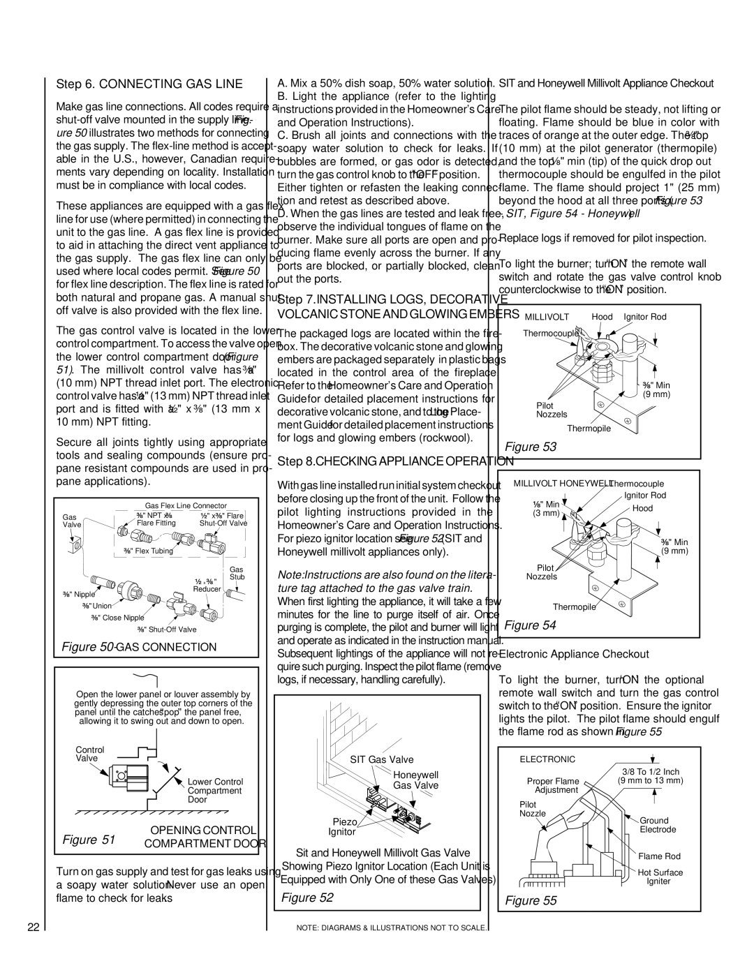
Make gas line connections. All codes require a shut-off valve mounted in the supply line. Fig- ure 50 illustrates two methods for connecting the gas supply. The flex-line method is accept- able in the U.S., however, Canadian require- ments vary depending on locality. Installation must be in compliance with local codes.

These appliances are equipped with a gas flex line for use (where permitted) in connecting the unit to the gas line. A gas flex line is provided to aid in attaching the direct vent appliance to the gas supply. The gas flex line can only be used where local codes permit. See Figure 50 for flex line description. The flex line is rated for both natural and propane gas. A manual shut off valve is also provided with the flex line.

The gas control valve is located in the lower control compartment. To access the valve open the lower control compartment door (Figure 51). The millivolt control valve has a ³⁄₈" (10 mm) NPT thread inlet port. The electronic control valve has a ¹⁄₂" (13 mm) NPT thread inlet port and is fitted with a ¹⁄₂" x ³⁄₈" (13 mm x 10 mm) NPT fitting.

Secure all joints tightly using appropriate tools and sealing compounds (ensure pro- pane resistant compounds are used in pro- pane applications).


Gas Flex Line Connector


Gas

³

" NPT x ³

¹ " x ³

" Flare

Valve

Flare Fitting

Shut-Off Valve


³ " Flex Tubing


Gas


¹

x ³ "

Stub


³ " Nipple

Reducer


³ " Union


³ " Close Nipple


³

" Shut-Off Valve


Figure 50- GAS CONNECTION


Open the lower panel or louver assembly by

gently depressing the outer top corners of the

panel until the catches “pop” the panel free,

allowing it to swing out and down to open.

Control


Valve


Lower Control


Compartment


Door

Figure 51

OPENING CONTROL

COMPARTMENT DOOR

Turn on gas supply and test for gas leaks using a soapy water solution. Never use an open

flame to check for leaks.

A. Mix a 50% dish soap, 50% water solution. B. Light the appliance (refer to the lighting instructions provided in the Homeowner's Care and Operation Instructions).

C. Brush all joints and connections with the soapy water solution to check for leaks. If bubbles are formed, or gas odor is detected, turn the gas control knob to the “OFF” position. Either tighten or refasten the leaking connec- tion and retest as described above.

D. When the gas lines are tested and leak free, observe the individual tongues of flame on the burner. Make sure all ports are open and pro- ducing flame evenly across the burner. If any ports are blocked, or partially blocked, clean out the ports.

Step 7. INSTALLING LOGS, DECORATIVE VOLCANIC STONE AND GLOWING EMBERS

The packaged logs are located within the fire- box. The decorative volcanic stone and glowing embers are packaged separately in plastic bags located in the control area of the fireplace. Refer to the Homeowner's Care and Operation Guide for detailed placement instructions for decorative volcanic stone, and to the Log Place- ment Guide for detailed placement instructions for logs and glowing embers (rockwool).

Step 8. CHECKING APPLIANCE OPERATION

With gas line installed run initial system checkout before closing up the front of the unit. Follow the pilot lighting instructions provided in the Homeowner's Care and Operation Instructions. For piezo ignitor location see Figure 52 (SIT and Honeywell millivolt appliances only).

Note: Instructions are also found on the litera- ture tag attached to the gas valve train. When first lighting the appliance, it will take a few minutes for the line to purge itself of air. Once purging is complete, the pilot and burner will light and operate as indicated in the instruction manual. Subsequent lightings of the appliance will not re- quire such purging. Inspect the pilot flame (remove logs, if necessary, handling carefully).

SIT Gas Valve

Honeywell

Gas Valve

Piezo

Ignitor

Sit and Honeywell Millivolt Gas Valve

Showing Piezo Ignitor Location (Each Unit is Equipped with Only One of these Gas Valves)

Figure 52

NOTE: DIAGRAMS & ILLUSTRATIONS NOT TO SCALE.

SIT and Honeywell Millivolt Appliance Checkout

The pilot flame should be steady, not lifting or floating. Flame should be blue in color with traces of orange at the outer edge. The top ³⁄₈" (10 mm) at the pilot generator (thermopile) and the top ¹⁄₈" min (tip) of the quick drop out thermocouple should be engulfed in the pilot flame. The flame should project 1" (25 mm) beyond the hood at all three ports (Figure 53

- SIT, Figure 54 - Honeywell)

Replace logs if removed for pilot inspection.

To light the burner; turn “ON” the remote wall switch and rotate the gas valve control knob counterclockwise to the “ON” position.

MILLIVOLT

Hood Ignitor Rod

Thermocouple


³⁄₈" Min (9 mm)

Pilot Nozzels

Thermopile

Figure 53

MILLIVOLT HONEYWELL Thermocouple

¹⁄₈" Min

Ignitor Rod

Hood

(3 mm)


³⁄₈" Min (9 mm)

Pilot

Nozzels

Thermopile

Figure 54

Electronic Appliance Checkout

To light the burner, turn ‘ON’ the optional remote wall switch and turn the gas control switch to the “ON” position. Ensure the ignitor lights the pilot. The pilot flame should engulf the flame rod as shown in Figure 55.

ELECTRONIC

3/8 To 1/2 Inch

Proper Flame(9 mm to 13 mm) Adjustment

Pilot

Nozzle

Ground

Electrode

Flame Rod

Hot Surface

Igniter

Figure 55

Page 22
Image 22
TOA Electronics 600 installation instructions Connecting GAS Line

600 specifications

TOA Electronics, a leading manufacturer in the audio and communication equipment industry, has built a reputation for delivering high-quality products designed for commercial and professional applications. One of their standout offerings is the TOA 600 series of amplifiers, which combines power, clarity, and reliability, catering to a diverse range of sound reinforcement needs.

The TOA 600 series amplifiers are engineered with a wide power range, accommodating various installations from small venues to large auditoriums. This versatility is complemented by advanced technologies that enhance audio performance. The amplifiers boast a compact design, making them easy to integrate into existing sound systems without occupying excessive space.

One of the key features of the TOA 600 series is its high efficiency. Utilizing Class D amplification technology, these amplifiers deliver clear and powerful audio while consuming less energy than traditional analog amplifiers. This not only reduces operational costs but also minimizes heat generation, enhancing the long-term reliability of the equipment.

Another notable characteristic of the TOA 600 series is its built-in digital signal processing (DSP) capabilities. This technology allows users to optimize sound quality in real-time by adjusting parameters such as equalization, compression, and limiting. Users can create tailored sound profiles that suit specific environments or applications, ensuring optimal audio clarity and consistency.

The TOA 600 series also includes extensive protection circuits that safeguard the amplifier against common faults like overcurrent, overload, and overheating. This ensures durability and serviceability, making it a preferred choice for professionals who require dependable audio solutions.

Additionally, the amplifiers support multiple input options, including balanced XLR inputs and unbalanced RCA connectors, allowing for seamless integration with a variety of audio sources such as microphones, mixers, and playback devices. The built-in network capability also facilitates remote control and monitoring, providing users with greater flexibility and convenience.

Overall, the TOA 600 series amplifiers are a testament to TOA Electronics' commitment to quality and innovation in the audio industry. With their advanced features, robust construction, and user-friendly interface, these amplifiers are ideal for anyone seeking reliable and high-performance audio solutions for commercial or professional applications. Whether in schools, venues, or corporate environments, the TOA 600 series amplifiers deliver unparalleled sound quality and reliability.