Step 3. INSTALL THE VENT SYSTEM

General Information

These instructions should be used as a guide- line and do not supersede local codes in any way. Install vent according to local codes, these instructions, the current National Fuel Gas Code (ANSI-Z223.1) in the USA or the current standards of CAN/CGA-B149.1 and - B149.2 in Canada.

These fireplaces are designed, tested and listed for operation and installation with, andonlywith,SecureVent(SV4.5)Direct Vent System Components, Secure Flex

Flexible Vent Components manufactured by Security Chimneys International. These approved vent system components are la- beled for identification. DO NOT use any other manufacturer's vent components with these appliances. These fireplaces must be vented directly to the outside.

The vent system may not service multiple appli- ances, and must never be connected to a flue serving a solid fuel burning appliance. The vent pipe is tested to be run inside an enclosing wall (such as a chase). There is no requirement for inspection openings in the enclosing wall at any

Remove and discard the cover plate. Reinstall and securely tighten all four cover plate screws. Re-secure the lintel to the rear wall of the firebox.

WARNING: FAILURE TO REINSTALL AND SECURELY TIGHTEN COVER PLATE SCREWS COULD RESULT IN LEAKAGE OF FLUEPRODUCTSINTOTHELIVINGSPACE. VENTCOVERPLATEANDVENTSEALPLATE MUST REMAIN SECURELY INSTALLED ON UNUSED VENT COLLAR. FAILURE TO DO SO COULD RESULT IN LEAKAGE OF FLUE PRODUCTS INTO LIVING SPACE.

ON D-500/600/800 SERIES MODELS

(COMBINED TOP AND REAR VENT UNITS)

TOP VENT SEAL & COVER PLATE

REMOVAL WHEN USING THE TOP VENT

(OUTSIDE UNIT)

VENT SEAL PLATE


GASKET


SECURING

CABINET TOP

SCREWS

TOP VENT

FIREBOX TOP

VENT

COVER PLATE COVER PLATE SECURING SCREWS

VENT RESTRICTOR INSTALLATION


(TOP VENT)

A vent restrictor may be needed when

vertically terminating the vent system above

the roof (when using the appliance top

vent), install vent restrictor in the top vent

of the fireplace outlet on D-500/600/800 and

DT-500/600/800 series models.

If needed, install the restrictor orientated as

shown, either from inside or outside the unit,

in the inner fireplace collar.

RESTRICTOR


INNER


FIREPLACE


COLLAR

APPLIANCE TOP


VENT OUTLET

Figure 15


VENT RESTRICTOR INSTALLATION

(REAR VENT)

A vent restrictor may be needed when horzontally terminating the vent system from the rear of the appliance (when using the applliance rear vent), install vent restrictor in the rear vent of the fireplace outlet on D-500/600/800 and DR-500/600/800 series models, in any installation that has a vertical vent run in

of the joints in the vent pipe.

Preparing the Appliance Vent Collar on D-500/600/800 Series (Combined Top and Rear Vent) Models

(INSIDE UNIT)

Figure 13

CROSS SECTION

excess of three feet (0.914 meters).

If needed, install the restrictor orientated as shown, either from inside or outside the unit, in the inner fireplace collar.

INNER FIREPLACE

APPLIANCE REAR

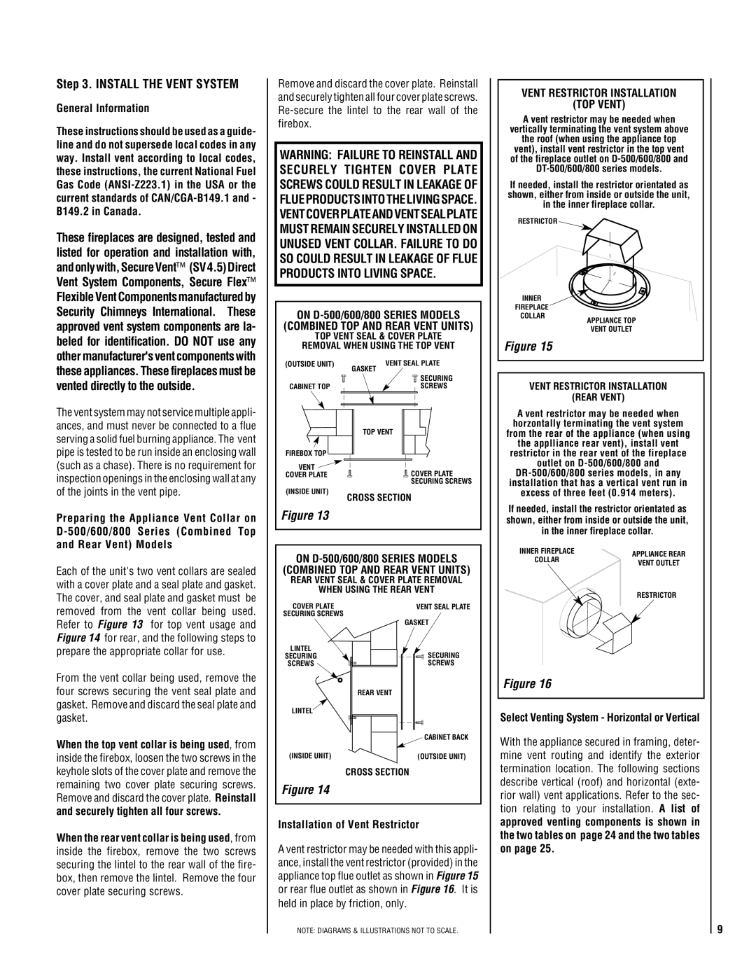
Each of the unit's two vent collars are sealed with a cover plate and a seal plate and gasket. The cover, and seal plate and gasket must be removed from the vent collar being used. Refer to Figure 13 for top vent usage and Figure 14 for rear, and the following steps to prepare the appropriate collar for use.

From the vent collar being used, remove the four screws securing the vent seal plate and gasket. Remove and discard the seal plate and gasket.

When the top vent collar is being used, from inside the firebox, loosen the two screws in the keyhole slots of the cover plate and remove the remaining two cover plate securing screws. Remove and discard the cover plate. Reinstall and securely tighten all four screws.

When the rear vent collar is being used, from inside the firebox, remove the two screws securing the lintel to the rear wall of the fire- box, then remove the lintel. Remove the four cover plate securing screws.

ON D-500/600/800 SERIES MODELS

(COMBINED TOP AND REAR VENT UNITS)

REAR VENT SEAL & COVER PLATE REMOVAL

WHEN USING THE REAR VENT

COVER PLATE

VENT SEAL PLATE

SECURING SCREWS

GASKET


LINTEL

SECURING

SECURING

SCREWS

SCREWS


REAR VENT

LINTEL


CABINET BACK

(INSIDE UNIT)

(OUTSIDE UNIT)

CROSS SECTION

Figure 14

Installation of Vent Restrictor

A vent restrictor may be needed with this appli- ance, install the vent restrictor (provided) in the appliance top flue outlet as shown in Figure 15 or rear flue outlet as shown in Figure 16. It is held in place by friction, only.

NOTE: DIAGRAMS & ILLUSTRATIONS NOT TO SCALE.

COLLAR

VENT OUTLET


RESTRICTOR

Figure 16

Select Venting System - Horizontal or Vertical

With the appliance secured in framing, deter- mine vent routing and identify the exterior termination location. The following sections describe vertical (roof) and horizontal (exte- rior wall) vent applications. Refer to the sec- tion relating to your installation. A list of approved venting components is shown in the two tables on page 24 and the two tables on page 25.

9

Page 9
Image 9
TOA Electronics 600 installation instructions Install the Vent System, Combined TOP and Rear Vent Units

600 specifications

TOA Electronics, a leading manufacturer in the audio and communication equipment industry, has built a reputation for delivering high-quality products designed for commercial and professional applications. One of their standout offerings is the TOA 600 series of amplifiers, which combines power, clarity, and reliability, catering to a diverse range of sound reinforcement needs.

The TOA 600 series amplifiers are engineered with a wide power range, accommodating various installations from small venues to large auditoriums. This versatility is complemented by advanced technologies that enhance audio performance. The amplifiers boast a compact design, making them easy to integrate into existing sound systems without occupying excessive space.

One of the key features of the TOA 600 series is its high efficiency. Utilizing Class D amplification technology, these amplifiers deliver clear and powerful audio while consuming less energy than traditional analog amplifiers. This not only reduces operational costs but also minimizes heat generation, enhancing the long-term reliability of the equipment.

Another notable characteristic of the TOA 600 series is its built-in digital signal processing (DSP) capabilities. This technology allows users to optimize sound quality in real-time by adjusting parameters such as equalization, compression, and limiting. Users can create tailored sound profiles that suit specific environments or applications, ensuring optimal audio clarity and consistency.

The TOA 600 series also includes extensive protection circuits that safeguard the amplifier against common faults like overcurrent, overload, and overheating. This ensures durability and serviceability, making it a preferred choice for professionals who require dependable audio solutions.

Additionally, the amplifiers support multiple input options, including balanced XLR inputs and unbalanced RCA connectors, allowing for seamless integration with a variety of audio sources such as microphones, mixers, and playback devices. The built-in network capability also facilitates remote control and monitoring, providing users with greater flexibility and convenience.

Overall, the TOA 600 series amplifiers are a testament to TOA Electronics' commitment to quality and innovation in the audio industry. With their advanced features, robust construction, and user-friendly interface, these amplifiers are ideal for anyone seeking reliable and high-performance audio solutions for commercial or professional applications. Whether in schools, venues, or corporate environments, the TOA 600 series amplifiers deliver unparalleled sound quality and reliability.