GTS-820A Series
Page
General Handling Precautions
Maintenance for driving parts
Rotating the instrument and telescope
Storage in the case
Safety Cautions
Display for Safe Use
User
Exceptions from Responsibility
Laser Safety
Symbol marks while the laser is emitting
Mode Laser class
Labels
Contents
Correction for Refraction and Earth Curvature
APPENDIX-1
Standard Set Composition
Nomenclature and Functions
Nomenclature
Nomenclature and Functions
Nomenclature and Functions
Display
Operating Key
Laser is emitting
Waiting Laser is emitting Searching Laser is emitting
Laser is off
Function Key Soft Key
Display Soft Function
Meas
Mode
Mean
SET
Star key *key mode
2003 143040
2003-10-10
Screen
+00000
Set audio mode
512KB 315KByte 1882KByte
Reticle illumination OFF/Low/Middle/High
OFF
Meaning of Tracking Indicator on or Flashing
Tracking Indicator
Operation
Auto Power Off
Data Output
Rotating Method
Rotating by H/V Shuttle and H/V Jog
Using together with RC-2II Remote Control System
Turn-round function
RC-2RII
Using connecting with Personal Computer PC
Commands Action of GTS-820A series
On / OFF
Power Connection
Unnecessary if on-board Ni-MH battery BT-56Q is used
Preparation for Measurement
Preparation for Measurement
Setting Instrument Up For Measurement
Reference Leveling and Centering the Instrument
Power Switch Key on
Password option
Choosing the first mode when turning on the instrument
2003-10-10
Battery Level Indicator
Parameters Setting Modes
Main Menu Icons
Vertical and Horizontal Angle Tilt Correction
Compensation of Systematic Error of Instrument
Resume Mode ON/OFF
How to Enter Numerals and Alphabet Letters
Pressing F1OFF key or F2ON key, select the resume mode
Operating procedure Option Display
How to insert a memory card
How to extract a memory card
Memory Card
Inclination of Prism and Measuring Error
Prism constant value 0mm
Prism constant value 30mm
Distance error is
Angle error is
Example
Prism type-2 Normal prism
Press the F1 key. The mode will be Automatic tracking mode
Automatic Tracking / Automatic Collimation
Automatic Tracking
Instrument searches the prism and tracks Automatically
Normal Status Mode
Automatic tracking
Tracking
Waiting status
Automatic Collimation
NEZ 0SET Hold P1↓
PPM
Range of Laser for Auto-tracking and Auto-collimating
Setting Parameters for Auto-Tracking
Setting Items
Items Selecting item Contents
Search Patterns
Wait Time
Tracking Speed
Reflector type
Prediction operating time
How to set the parameters
Operating procedure Option
Standard Measurement Mode
Reference How to Collimate
Angle Measurement
Measuring Horizontal Angle Right and Vertical Angle
Switching Horizontal Angle Right/Left
Setting by Holding the Angle
Measuring from the Required Horizontal Angle
Vertical Angle Percent Grade% Mode
Press the F1TURN key
Press the F3 key
For example 93 Angle
Input the horizontal angle to be rotated,
Setting of the Atmospheric Correction
Setting of the Correction for Prism Constant
Distance Measurement
Distance Measurement Continuous Measurement
Distance Measurement Single/N-times Measurement
2Measuring Method
Meas Mode NEZ P1↓
Fine / Coarse Measuring Mode
Display value = Measured distance -Standard Preset distance
Stake Out S-O
Setting Coordinate Values of Occupied Point
Operating procedure Operation Display
Press F3NEZ key
Press F5SET key
ENT Standard Measurement Mode
Exitbs
PSM PPM Turn HT
Setting of the Instrument Height / Prism Height
PSM PPM Meas Mode VH
Execution of Coordinate Measuring
Collimate target B Press F3NEZ key.*3 Measuring starts
PPM Meas Mode VH SD
Mode will automatically return to the distance
Slope distance mode V, HR,SD
Coordinate mode Z, HR
Measurement will be started
Standard Measurement Mode
Program Modes
Program Modes
F6MORE key
Line Store Offset REM EXT.LINK MLM More
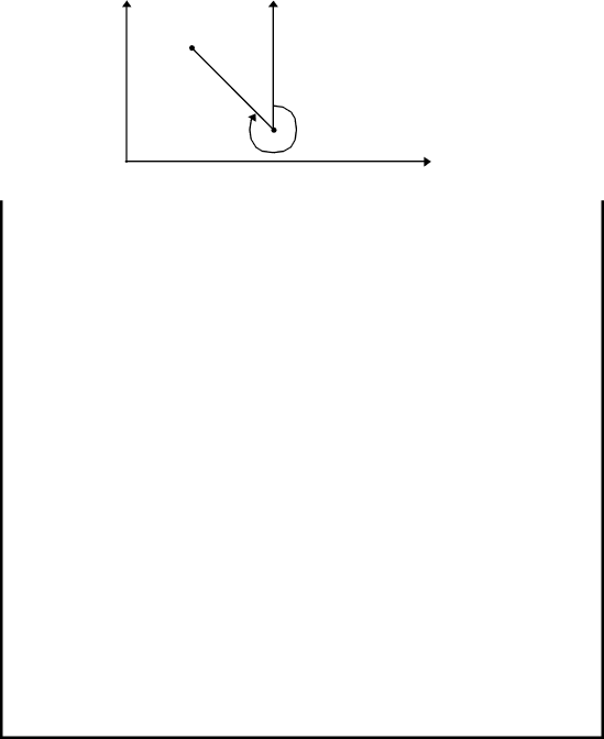
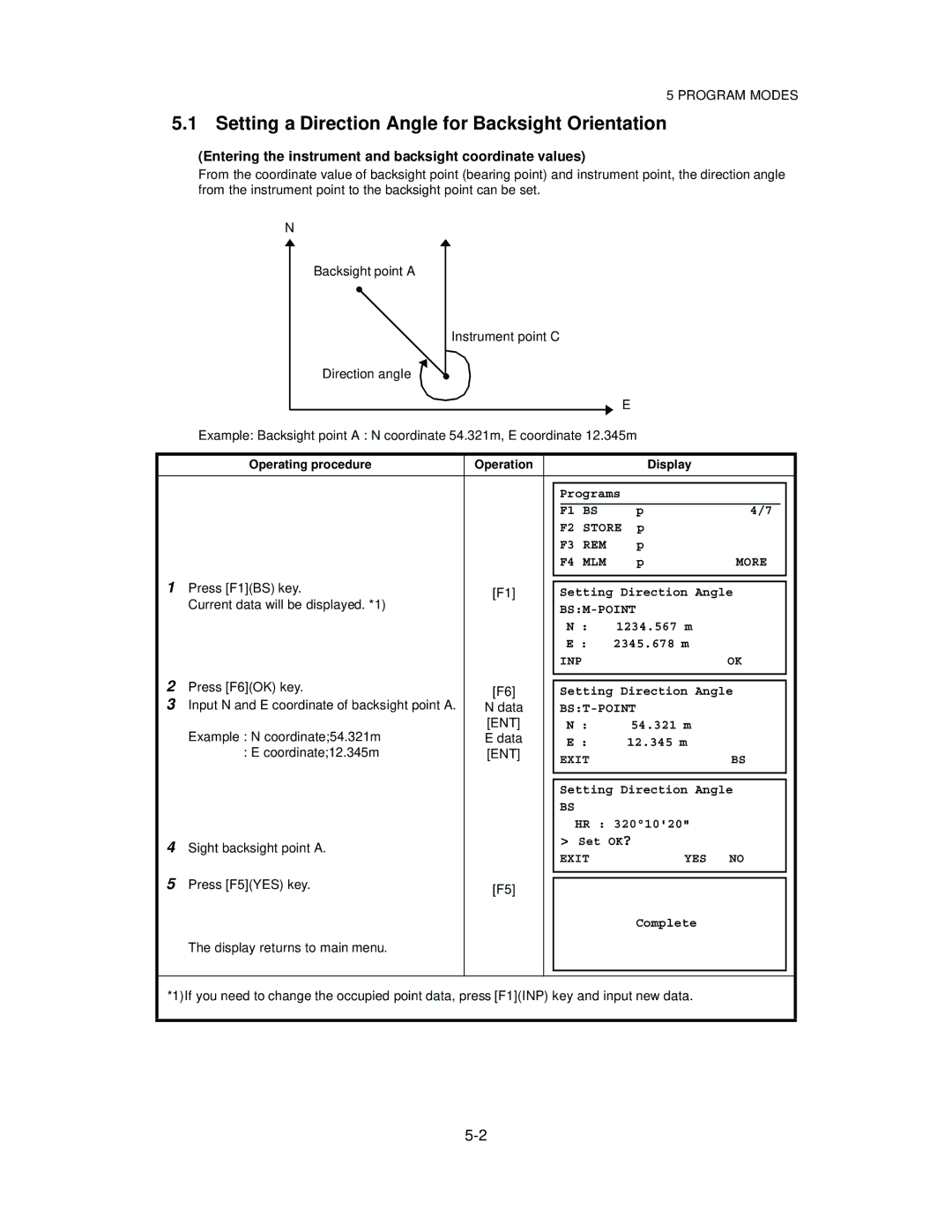
Setting a Direction Angle for Backsight Orientation
Entering the instrument and backsight coordinate values
Retaining a Coordinate STORE- NEZ
SET OK? YES
Store REM MLM More
YES no
Remote Elevation measurement REM
With prism height h input Example h=1.5m
2Without prism height input
Measset REM
Press F2NO key
Horizontal distance HD between
SET REM
Exit HD REM
Exit HD
Missing Line Measurement MLM
Press F4MLM key
Press F1A-B, A-C key
Measset MLM
Exit HD MLM
1To return to main menu, pressF1EXIT and F5YES key
Line Measurement Line
Line PT a
Meas SET Line PT B
Line PT B Meas SET
Meas SET Line
Line Point
Exit SET Line
Exit Next
Distance measurement mode of the offset measurement
Offset measurement Offset
Outputting the Measurement Data
Line Offset EXT.LINK More
Angle Offset
To get to the next page of programs
Press F2OFFSET key
Press F1ANGLE Offset key
Measht Angle Offset
Next NEZ
Distance Offset Measurement
Offset Measurement
Press F2DIST. Offset key
Previous offset value screen will appear
Exitbs DIST. Offset Meas
Plane Offset Measurement
Press F3PLANE Offset key
Measurement screen of three points on a
Plane will be shown
Measht Plane Offset
Column Offset Measurement
SET Column Offset
Setting for the communication
1Setting communication course
External Link
Starting compatible communication program of AP-L1A
2Setting Parameters of Cable RS-232C
Parameters
CABLE/RADIO MODEM/RC SET ↑ ↓ Exit
3Setting Parameters of RC
Speed
4Setting Parameters for Radio Modem
REC-A
REC-B
Channel SET Exit
Channel setting display is provided Only for certain market
Carrying out Communication
Channel
SET Exit REC Type REC-A
Memory Manage Modes
View Internal Memory and Card Memory Status
Operating procedure Operation Display Proceed Chapter
Refer to .9 How to Enter Numerals and Alphabet Letters
Protect a File
Rename a File
Deleting a File
Copy a File
Initializing Memory
Setting of Protocol
Communication Modes
Data File
Data File Out
Parameters Setting Mode
Parameter Setting Options
Menu Selecting Item Contents
Parameters for Measurement and Display
Meter /FEET
OFF / MEM.ON
NEZ / ENZ
Setting parameters for RS232C
Setting parameter for RC
Parameters for communication
Serial port
ETX
Crlf
Setting Parameters
Password Option
Establishing a Password
Turning OFF the Password
Turning OFF the Password Option
Exit Change On OFF
Changing a Password
Changing the Password
OFF Exit Change
Check and Adjustment
Checking and Adjusting of Instrument Constant
Checking the Optical Axis
Direction confirmation Do not move V direction
Check and Adjustment
Checking/Adjusting the Theodolite Functions
Pointers on the Adjustment
Checking /Adjusting the Plate Level
Checking /Adjusting the Circular Level
Adjustment
Check
Adjustment of the Vertical Cross-hair
Collimation of the Instrument
Checking / Adjusting the Optical Plummet Telescope
Adjustment of Compensation Systematic Error of Instrument
Skipset
Skipset Face
Skipset Face LEVEL±10
Press F2 key
Correction values are displayed
Exit OFF
Press F6OFF key
How to adjust the date and time
How to Set the Instrument Constant Value
Press F4 Instrument constant key
Press F5 YES key
Input value and press ENT key Value
Reference Frequency Checking Mode
Press the F6 ↓ key to get to next page on
Press the F1 key
Beam will be emitted
Inspection and Adjustment of Optic Axis for Auto -Tracking
Normal position Centers of prism
Turn Meas
Adj Tracking Axis Wait Set OK?
Setting the Prism Constant Value
Setting the Prism Constant Value
Setting Atmospheric Correction
Setting of Atmospheric Correction Value
Setting Atmospheric Correction
How to Set Temperature and Pressure Value Directly
How to Set the Atmospheric Correction Value Directly
11-2
Atmospheric Correction Chart For your reference
11-4
11-5
Correction for Refraction and Earth Curvature
Distance Calculation Formula
Correction for Refraction and Earth Curvature
Power Source and Charging
Rechargeable Battery BT-56Q
13-2
DETACH/ATTACH of Tribrach
DETACH/ATTACH of Tribrach
Detachment
Attachment
Battery System
Case of Rechargeable Battery BT-56Q
Case of External battery Pack
Prism System
Prism System
Precautions
Precautions
Error Displays
Error Displays
Over
Special Accessories
Cigarette battery charger BC-9 for BT-3Q
Battery charger BC-6 for BT-3L
Prism unit case, Model
Gadget case, Model
Power cord PC-6 For BT-3L, AC-6
Large capacity battery pack BT-3L
Power cord PC-5
Aluminum extension leg tripod, Type E
Specifications
Specifications
Automatic Tracking / Collimating
Manual Driving
Distance measurement
Atmospheric conditions
Condition
Electronic Angle Measurement
Tilt Correction
Others
Computer unit
Display and keyboard
Battery Charger BC-27BR / BC-27CR
Appendix
Dual Axis Compensation
Appendix
APPENDIX-2
Precaution when Charging or Storing Batteries
Recharging
Discharge
Storage
APPENDIX-4
END User License Agreement
Embedded Products
EMC Notice
Page
GTS-820A series