42/50HP95 *web
Integrated High Definition Plasma Television
Tune Into Safety
Safety Precautions
It Makes a Difference Where Your TV Stands
Issue
Installation, Care, and Service
Important Safety Instructions
Service
Important notes about your Plasma TV
FCC Declaration of Conformity Compliance Statement Part
Contents
112
101
107
See Important notes about your Plasma TV on
Features of your new TV
Introduction
Welcome to Toshiba
Introduction
Green and Red LEDs
Connecting your TV
TV front and side panel controls and connections
Exit Press to close an on-screen menu instantly
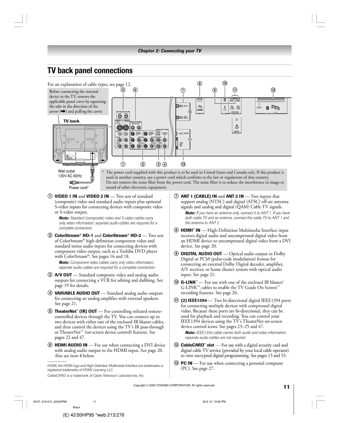
Also see item 8 below
£ PC in For use when connecting a personal computer PC. See
TV back panel connections
3 4 !£
Overview of cable types
To view encrypted digital channels
¥ In Canada, call TCL Customer Service at
For more information, call your local cable operator
You will need
Connecting a camcorder
Connecting a VCR and antenna or Cable TV no Cable box
From Cable TV
Connecting a VCR and Cable box
On Screenª recording features
To view basic and premium Cable channels
From satellite dish
Connecting a VCR and satellite receiver
Select the ColorStream HD-1 video input source on the TV
From antenna
¥ If your DVD player has component video, see
To view basic channels and access the TVÕs features
To view premium Cable channels
To view the DVD player
From antenna or Cable
Your TV has ColorStream component video inputs
To view antenna or Cable channels
To record a TV program while watching a DVD
Video OUT terminal does not output the POP picture
Connecting two VCRs
To view VCR
To dub or edit from VCR 1 to VCR
To connect an Hdmi device, you will need
Connecting an Hdmi or a DVI device to the Hdmi input
One Hdmi cable type a connector per Hdmi device
See ÒSetting the Hdmi audio modeÓ on
To control the audio
Connecting a digital audio system
Connecting an analog audio system
TV’s Digital Audio OUT terminal outputs a Dolby
To control the devices
TheaterNet on-screen device control
To connect the IR blaster cable
Using TheaterNet on-screen device control
Connecting IEEE1394 video devices
Using analog-compatible IEEE1394 devices
Supported signals
IEEE1394 device initialization
When you connect a D-VHS or Avhd device to the TV
Highlight the device you want to edit and press Enter
IEEE1394 device management
To edit the IEEE1394 device information
See Chapter
For details on setting up the TV Guide On Screenª system
Link connection
To connect to the G-LINK ª terminal
Pin assignment for RGB/PC terminal
Connecting a personal computer PC
Signal names for mini D-sub 15 pin connector
Learning about the remote control
Using the remote control
Point remote control toward remote sensor on front of TV
Remote control effctive range
Device mode control after programming
Installing the remote control batteries
To install the remote control batteries
Power
Remote Control functional key chart
PVR
Functions
Device code setup Searching and sampling the code
Device
To reset the volume controls to the original device mode
Using the volume lock feature
Operational feature reset
Repeatedly press Mode to select CABLE/SAT mode
Brand Code
Multi-brand remote control device codes
VCRs/PVRs
Cable boxes
DVD players
CD players
Receivers
Laser disks
Picture Shift On / Off Gray Level 1 / 2 Reverse White
Menu layout and navigation
Main menu layout
To close a menu instantly, press Exit
Setup / Installation menu layout
Navigating the menu system
Press Menu to open the menu system
To set up the TV Guide On Screenª system
TV Guide On Screen setup
Setting up the TV Guide On Screen system
On next
For additional details, see
Setting up the TV Guide On Screen system
If your VCR did not
TV Guide On Screen Reminder
To select the menu language
Setting up your TV
To configure the ANT 1 and ANT 2 input sources
To program channels automatically
Programming channels into the TV’s channel memory
Programming channels automatically
Manually adding and deleting channels in the channel memory
To add a channel to the selected Favorite Channel set
To clear your favorite channel lists
To add and delete channels in the Favorite Channels sets
List
To remove a device from TheaterNet
Setting up and using TheaterNet on-screen device control
Setting up TheaterNet
To set up TheaterNet device control
To view another source
Using the TheaterNet control icons
To select the deviceÕs control icons directly
To close the on-screen control icons
Miscellaneous audio devices
TheaterNet IR device codes
Amplifiers
Laser disk players
VCRs
Video accessory Hdtv decoder
MEI
To set the Avhd device skip time
Setting the time and date
Setting the Hdmi audio mode
To select the Hdmi audio mode
To return to normal viewing
To view the digital signal meter
To view the CableCARD ª menu
To close the screen and return to the Terrestrial menu
To check the system status
To close the screen and return to the Installation menu
To cancel the reset
Viewing the system status
Rating, stereo, HDTV, new episode
TV Guide On Screen system includes the following features
While watching TV, press TV Guide on the remote control
To open the TV Guide On Screenª system
REC Split
TV Guide On Screen remote control functions
Navigating the TV Guide On Screen system
Menu Info TV Guide Enter Down
To lock/unlock the Video Window
Video Window
Panel Menus
Show is presented in high-definition TV, if available
Info Box
TV Guide On Screen Icons
Hdtv
Listings screen
TV Guide On Screen Services
Example Category search
Search screen
To edit or delete a keyword
List of all matching shows for that keyword is displayed
To view a recording, you can do one of the following
For additional details, see ÒRecord featuresÓ on
Recordings screen
To choose the way recordings are displayed
Schedule screen
Record features
Set a show to Record from a panel menu
Highlight NEW Manual Recording and press
Don’t Record This Show-Cancels the Recording
You can choose to start or cancel recording Record Daily
Default highlighted item in the notification banner is
Remind features
Reminder notification banner
Change channel display
Setup screen
Change system settings
Remind defaults
Change default options
General defaults
Record defaults
¥ The source can be Òhidden.Ó See page 70 for details
Using the TV’s features
Selecting the video input source to view
To select the video input source to view
To clear the input labels
Labeling the video input sources
Game Console
To label the video input sources
To tune to a channel in Browse mode
Tuning channels
Using the Channel Browser
To toggle between Browse mode and Select mode
Adding channels to the channel history
To set a channel as Home using the remote control
To set a channel as Home using the menus
To tune to the Home channel
Switching between two channels using SurfLock
Tuning channels Tuning your favorite channels
Tuning to the next programmed channel
Switching between two channels using Channel Return
PIC Size
Selecting the picture size
You can view many program formats in a variety of picture
To select the picture size
Full picture size for 169 480i, 480p source programs only
TheaterWide 1 picture size For 43 format program
TheaterWide 2 picture size for letter box programs
To turn off the auto aspect ratio feature
Using the auto aspect ratio feature
To set the scroll settings
To turn on the auto aspect ratio feature
To set the Cinema Mode to Video
Selecting the cinema mode 480i signals only
To set the Cinema Mode to Film
Cinema Mode field, select Film
To close the POP window and tune to the highlighted window
Using the POP features
Using the POP double-window feature
To display a program in the POP window
Example Press
Switching the speaker audio main or POP
POP double-window aspect ratio
Highlight the window for the channel you want to view
Using the Freeze feature
Using the favorite channel scan feature
To scan and tune your favorite channels
Adjusting the picture quality
Adjusting the picture
Selecting the picture mode
To select CableClear/DNR preferences
Using CableClear /DNR digital noise reduction
Selecting the color temperature
To select the color temperature
To select dynamic contrast preferences
Using Mpeg noise reduction
Using dynamic contrast
To select the Mpeg noise reduction level
Advanced closed captions
Using the closed caption mode
To select digital closed captions
Digital closed captions
Selecting stereo/SAP broadcasts
Adjusting the audio
Using the digital audio selector
Muting the sound
To turn on the StableSound¨ feature
Adjusting the audio quality
Using the StableSound feature
To adjust the audio quality
Selecting the optical audio output format
Using the SRS WOW surround sound feature
Turning off the built-in speakers
Memory card specifications
Using the memory card Jpeg picture viewer/MP3 audio player
Press to rotate the large picture 90 clockwise
Using the Jpeg picture viewer
To view digital photos on your TV
Press x to rotate the large picture 90 counterclockwise
Using the Jpeg picture viewer
Using the MP3 audio player
Navigate to the rewind Pause, fast forward, skip
Volume, and mute buttons, and then press Enter
Memory card care and handling
Press yzx to
Setting the sleep timer
Setting the On/Off Timer
Picture Shift
Using the PC setting feature
Using the Long Life feature
To set the gray level of the sidebars
Gray Level White
Reverse
To display the white pattern
To display TV setting information on-screen
Understanding the auto power off feature
Understanding the last mode memory feature
Displaying TV setting information on-screen using Recall
Changing your PIN code
Using the Locks menu
Entering the PIN code
If you cannot remember your PIN code
Independent rating system for broadcasters
Blocking TV programs and movies by rating V-Chip
To block and unblock TV programs and movies
Press z to highlight Edit Rating Limits and press Enter
Locking video inputs
Blocking channels
Unlocking programs temporarily
Using the panel lock feature
Using the GameTimer
Noisy picture
Troubleshooting
General troubleshooting
Black box on screen Poor color or no color POP problems
Sign of malfunction
Set to SAP mode
Closed caption problems
Caption feature
Not be what you intended to record. See pages 69
Symptom Solution Recording problems
Other problems
Will be locked on the channel that is currently recording
Setup
TV Guide On Screen FAQs
105
On Screen ª system?
TV Guide On Screen FAQs
Edid = Enhanced-Extended Display Identification
Specifications
Appendix
Your Responsibility
Limited United States Warranty
Limited One 1 Year Warranty on Parts and Labor
How to Obtain Warranty Service
109
Limited Canada Warranty
110
111
100
Index
Channel programming
89-92
Picture adjustments
Remote control
Warranty 108
05-09
Manufactured by