R2SU
PM0015867010
Table of Contents
Others
Function Setup
Library
Introduction
About this product
Some differences Compatiblity
DVD-RAM discs for your personal library
For recording / playback Disc Mark Specification Remarks
Compatible discs
For playback only Disc Mark Specification Remarks
DVD-RAM discs with cartridges are recommended for recording
To protect recorded contents
Introduction Compatible discs
Recommended discs
Recommended disc
Standards
Recording conditions
Tested discs
Yes
Yes No
Discs and purposes
Index to parts and controls
DV input terminal
Input Select button
Input 2 jacks
To open or close the cover on the front panel
INPUT1/INPUT3 jacks
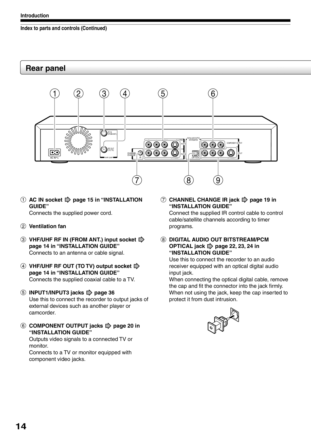
AC in socket page 15 in Installation Guide
Introduction Index to parts and controls
Component Output jacks page 20
Output jacks page 15, 17, 18, 22
Remote control
Menu
Return
Bit rate indicator
11PBC indicator
Program recording indicator
Remain Remaining space indicator
Dubbing indicator
Switching the display
SAP indicator
Progressive indicator
Before operating this recorder
Single sided
Turning the power off
Disc tray lock
Double sided
Reverse slow-motion
When title playback is completed
Forward slow-motion
Forward frame by frame playback
Easy Navi Enter Play Stop
Item selection
Press Easy Navi
To stop, press Stop
Opening a Quick Menu
To exit the Quick Menu
Hint on reading this manual
VCD Video CD
Is your DVD recorder ready?
Before recording
Recording
Disc initializing
When the programmed settings overlap
To check space remaining on a disc Press Remain
Initializing a DVD-RAM/RW disc Logical format
Recording Before recording
DVD-RAM physical format
During stop, press Setup
To cancel, select No, then press the Enter button
Press To select Start, then press Enter
Content Menu
Operation guidance of the remote control
Switching a language
Estimated end of the first line on
Erasing characters
Press Input Select repeatedly to select a recording source
Each time you press the button, the indicator alternates
Recording a TV program
To record a TV program or cable program with
Press / to select AV record quality, then press Enter
Press Adjust to select the setting number
Press the number buttons to select a channel to record
Open the lid
Press REC
Selecting the recording mode
Press Enter
Recording Recording a TV program
To change a TV channel to be recorded
To stop recording
To pause recording to omit an unnecessary portion
To view a TV program while recording another
Using the input jacks on the front of the recorder
Recording an external source
To record pictures from equipment connected to
When recording is completed, press Stop
Each time you press the button, the indicator changes
Input 1 jacks on the rear panel
Check the condition of the source equipment before playing
When recording from a camcorder
Recording Recording an external source
Press REC Menu to exit
When complete, press Enter
During stop, press REC Menu
REC Menu appears
DVD
Recording Programing a recording REC Menu Setting items
Suggestions for the picture quality setting
PCM
Press Quick Menu at on
Setting the details for every timer program
You can specify detail items for each of your timer program
Quick Menu is displayed
High rate save Genre setting
Recording Programing a recording REC Menu
Correcting a timer program
Adding a timer program
Deleting a timer program
Shifting a time period of a recording Time Shift
Recording Programing a recording REC Menu Remaining volume
To stop a programmed recording
Page
Press the appropriate number buttons to enter the PlusCode
Open the lid of the remote control, and press VCR Plus+
VCR Plus+ recording
For cable box or satellite receiver users
REC Menu disappears
After completing all your entries, press REC Menu
For details about items, see
To stop the Reservation Disc recording
Others
Load a DVD-RAM disc Press REC Menu
Important note
To delete recorded content
To protect recorded content
Enter Delete
Technical information
Play your favorite contents
Playback
Screen Protection
Information on playback
Playback
Playing recorded contents Content Menu
To pause playback still playback
Playing the digest Skip Search
Press / to select Play all ORG titles, then press Enter
Playing all titles original/playlist in a disc
After on page 53, press Quick Menu
Playback starts from the beginning of title
Press / to select an title, then press Enter
At on page 53, select a title chapter then press Quick Menu
Press / to select Title information, then press Enter
Viewing information of a loaded disc
Changing the order of the titles
Specified page appears
Playing a DVD-RW disc recorded in DVD-VR mode DVD-RW
To clear the number, press the Clear button
Playback starts
Playing a DVD video disc
Press Play
Press TOP Menu
Locating a title using the top menu
TOP Menu
Press / / / to select the title you want
Locate a scene you want by the following methods
Press Timeslip to exit this mode
Resume playback by pressing Pause or Play
Go back to the beginning of the TV program using Skip
Press Timeslip to exit
Playing at various speeds
During normal playback, press Picture Search
Playing in slow-motionDVD-RAM DVD-RW DVD-R DVD-VIDEO VCD
Press Slow during playback
Playback Playing at various speeds
Playing frame by frame DVD-RAM DVD-RW DVD-R DVD-VIDEO VCD
During playback, press Pause
Press Frame
Press the Play or Pause button
Press T.SEARCH
Locating by entering the number
Locating by entering the number of a desired section
Press the number buttons to enter a number of the section
Hour Minute Second
To enter 1 hour, 25 minutes, and 30 seconds
→ 1 → → 2 → 5 → → 3 →
Angle icon
Selecting the camera angle
To turn off the angle icon
Total number of angles Current selection
Selecting subtitles
Press to select Status, then press Adjust to select On
At , select Off by pressing the Adjust button
Press Subtitle during playback
Press Zoom
To cancel the zoom
Zooming a picture
Select a zoom point and magnification level
MTS Broadcast Compatibility
Selecting the sound
You can select a preferred language and a sound format
SAP Second Audio Program broadcast
Playback Selecting the sound Recorded sounds
Output sound conversion table
Disc
Viewing Jpeg files
Load a CD that contains Jpeg files
Viewing a specified photo single view
On the Content Menu Picture List
Jpeg files compatibility
To change the playback order
Playing MP3/WMA files
Load a CD that contains MP3/WMA files
VBR
Playable files
Press / / / to select a track or folder
CBR, VBR
Sub window program on the air or on the recording appears
During playback, press P in P
Press / / / to select the position of the sub window
You can shift the sub window in following 4 directions
Press Display
Operational status and setting details
You can confirm operational status and setting details
Press Display again
During playback or recording, press
Using the time bar
Playback Checking the current status and settings
Changing the location of the time bar
To play in random order Random play
Functions in the Quick Menu
To play repeatedly Repeat playback
Press Enter at the end of the segment point B
Playback Functions in the Quick Menu
To play in favorite order Memory playback
To turn off the bit rate display, select this item again
To display the current bit rate
To check information on a title
Page
Editing
You can create your own movie from your assembled scenes
Before editing
Editing
Playlist
Compile chapters in a desired order
Monday
Including three chapters Playlist
Title
Editing Before editing
Make the compiled chapters into a title Original. Dubbing
During stop, playback or recording, press
Content Menu Title List appears
Creating chapters
Press / / / to select a title
Press Play to start playback
Press / to select Chapter function, then press Enter
Press / to select Chapter editing, then press Enter
Editing Creating chapters
Repeat steps 6 to
When all chapter divisions have been made, press
Press / / / to select Divide, then press Enter
Picture pauses
Creating chapters automatically when recording
Editing chapter break
Merging chapters
Naming a chapter
Content Menu Main Menu appears
Press / to select Edit function, then press Enter
Cursor
Playlist editing
Repeat steps 4 to 6 to insert items
When all items have been inserted, press
To cancel the selection, see Canceling selection of a part
Editing Playlist editing
Confirming the title information
Canceling selection of a part
Using a part in a Playlist also in another Playlist
Correcting a Playlist
Press / to select Edit function, then press
From the Content Menu Title List, press
This will help to sort serials
Press / to select the item. Playlistevery week
Creating thumbnails Changing the picture on the Content Menu
Editing Creating thumbnails
Content Menu Create Thumbnail appears
100
Create Thumbnail
101
102
During playback or stop, press Content Menu
Content Menu High Speed Library Dubbing appears
You can jump to a page by specifying
To cancel copying halfway through the operation
103
Press / to select Del Selected Items
104
During playback or stop, press Edit Menu
Edit Main Menu
105
Press / to select the first title to merge
106
Press / to select Combine ORG Title, then press Enter
Edit Menu Combine ORG Title appears
Combining process starts
107
Perform steps 3 to 5 and select the second title
108
Display of option settings appears
DVD-Video finalizing process
Press To select DVD-Video Finalizing
Press / to select Next, then press
109
Press / / / to select
Press to select Next, then press Enter
Press / / / to select the chapter menu
110
Press / / / to select the title menu, then press Enter
Press / to select Yes or No then press
To cancel the finalize process DVD-RW
111
Press / to select DV Recording
Edit Menu DV Recording Option Setting appears
112
Press / / / to select Next, then press
Press / / / to make the settings
113
Library Menu
114
Editing DV recording Recording from a digital video camera
To facilitate your collecting
Basic operation of the Library system
Using Library data
116
Press Library
Searching for a disc
117
Checking remaining space on discs
118
Maintenance of Library data
Library Using Library data
Registering a disc manually
Erasing Library data
119
Forced deletion of disc numbers
Page
Function Setup
Press Setup
Customizing the function settings
During stop, press Setup
122
123
Function Setup Customizing the function settings
124
125
DVD player settings
126
127
128
Code
Picture/Audio settings
129
130
Display settings
131
Operational settings
132
133
DVD recorder operation
134
Management settings
135
Page
Others
138
Before calling service personnel
Power Playback
Connection to your TV
Program
139
Recording
Clock
Remote control
140
141
M1192kbps M2384kbps
Recording duration
142
DVD-RAM
Abbreviation Language
Language code list
143
Bengali, Bangla
MPEG2
Specification
144
145
Wireless remote control SE-R0123
Temperature 41F ~ 95F 5C ~ 35C Position Horizontal
Hour digital display
146
Time for Taking Action
How to Obtain Warranty Services
147
148
149
150
151

 page 15 in “INSTALLATION GUIDE”
 page 36
 page 20 in
 page 19 in
 page 22, 23, 24 in