|
|
|
|
|
|
|
|
|
| E6581268 ① | |
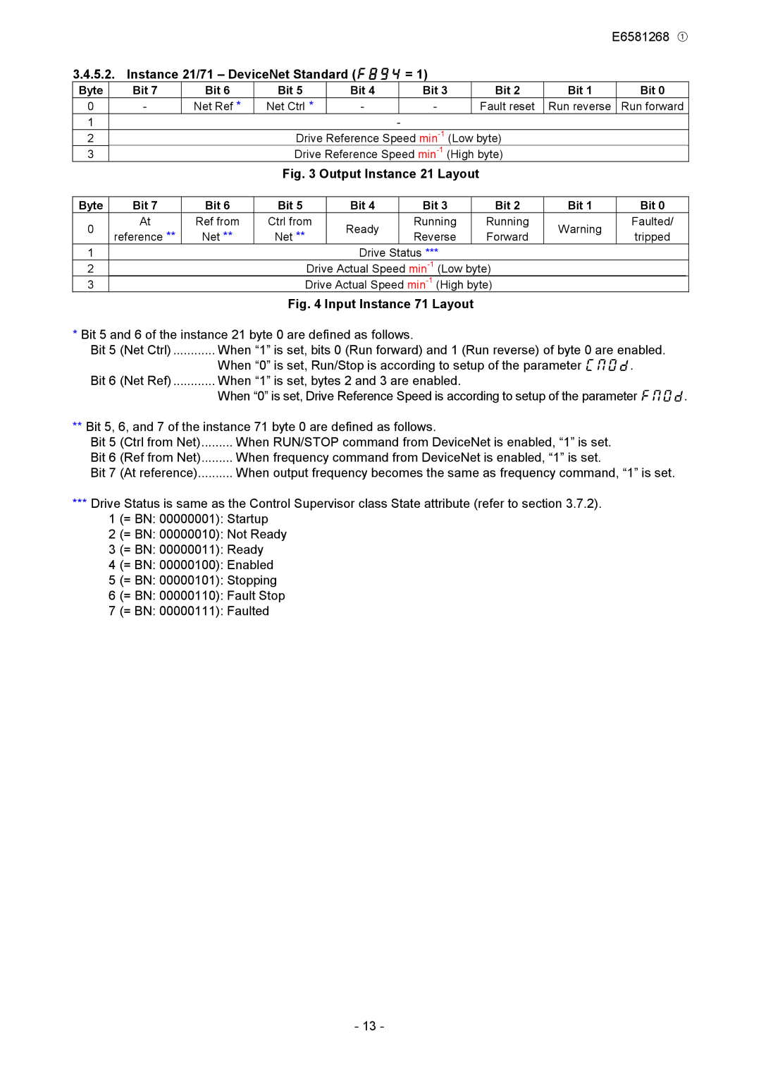
3.4.5.2. Instance 21/71 – DeviceNet Standard (f894 = 1) |
|
|
|
| |||||||
Byte | Bit 7 | Bit 6 | Bit 5 | Bit 4 |
| Bit 3 |
| Bit 2 | Bit 1 |
| Bit 0 |
0 | - | Net Ref * | Net Ctrl * | - |
| - |
| Fault reset | Run reverse |
| Run forward |
1 |
|
|
|
| - |
|
|
|
|
| |
2 |
|
| Drive Reference Speed |
|
|
| |||||
3 |
|
| Drive Reference Speed |
|
|
| |||||
|
|
| Fig. 3 Output Instance 21 Layout |
|
|
|
| ||||
|
|
|
|
|
|
|
|
|
|
| |
Byte | Bit 7 | Bit 6 | Bit 5 | Bit 4 |
| Bit 3 |
| Bit 2 | Bit 1 |
| Bit 0 |
0 | At | Ref from | Ctrl from | Ready |
| Running |
| Running | Warning |
| Faulted/ |
reference ** | Net ** | Net ** |
| Reverse |
| Forward |
| tripped | |||
|
|
|
|
|
| ||||||
1 |
|
|
| Drive Status *** |
|
|
|
| |||
2 |
|
| Drive Actual Speed |
|
|
| |||||
3 |
|
| Drive Actual Speed |
|
|
| |||||
Fig. 4 Input Instance 71 Layout
*Bit 5 and 6 of the instance 21 byte 0 are defined as follows.
Bit 5 (Net Ctrl) | When “1” is set, bits 0 (Run forward) and 1 (Run reverse) of byte 0 are enabled. |
| When “0” is set, Run/Stop is according to setup of the parameter cmod. |
Bit 6 (Net Ref) | When “1” is set, bytes 2 and 3 are enabled. |
| When “0” is set, Drive Reference Speed is according to setup of the parameter fmod. |
**Bit 5, 6, and 7 of the instance 71 byte 0 are defined as follows.
Bit 5 | (Ctrl from Net) | When RUN/STOP command from DeviceNet is enabled, “1” is set. |
Bit 6 | (Ref from Net) | When frequency command from DeviceNet is enabled, “1” is set. |
Bit 7 | (At reference) | When output frequency becomes the same as frequency command, “1” is set. |
***Drive Status is same as the Control Supervisor class State attribute (refer to section 3.7.2). 1 (= BN: 00000001): Startup
2 (= BN: 00000010): Not Ready
3 (= BN: 00000011): Ready
4 (= BN: 00000100): Enabled
5 (= BN: 00000101): Stopping
6 (= BN: 00000110): Fault Stop
7 (= BN: 00000111): Faulted
- 13 -