Table 11.8 Recommended Lugs.
At Terminal Bus # |
| Recommendation | ||
Vendor |
| Catalog # | ||
|
| |||
|
|
|
| |
1 |
|
| ||
| ILSCO |
| ||
2 | ||||
| ||||
|
|
| ||
3 |
| |||
|
|
| ||
|
|
|
| |
4 | ILSCO |
| ||
|
| |||
5 |
| |||
|
| |||
|
|
| ||
|
|
|
| |
6 |
|
| ||
|
|
| ||
7 |
| |||
|
| |||
|
|
| ||
8 |
| |||
|
|
| ||
| ILSCO |
|
| |
9 |
| |||
|
|
|
| |
10 |
|
| ||
|
|
| ||
11 |
|
| ||
|
| |||
|
|
| ||
12 |
|
| ||
|
|
| ||
|
|
|
| |
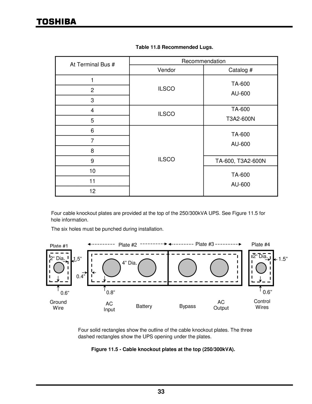
Four cable knockout plates are provided at the top of the 250/300kVA UPS. See Figure 11.5 for hole information.
The six holes must be punched during installation.
Plate #1
2“ Dia.
1.5”
0.4”
Plate #2 ![]()
![]() Plate #3
Plate #3 ![]()
4” Dia.
Plate #4
2“ Dia.
![]() 1.5”
1.5”
| 0.6” |
| 0.8” |
|
|
|
| 0.6” | |
|
|
|
|
|
| ||||
Ground |
| AC | Battery | Bypass | AC | Control | |||
Wire |
| Output | Wires | ||||||
Input | |||||||||
|
|
|
|
|
|
| |||
Four solid rectangles show the outline of the cable knockout plates. The three dashed rectangles show the UPS opening under the plates.
Figure 11.5 - Cable knockout plates at the top (250/300kVA).
33
