11.4 Grounding Wire
Be sure to ground the UPS as specified.
WARNING | Using the UPS without a proper ground will deteriorate the | |
insulation and may cause electric shock due to leakage currents. | ||
| ||
| The resistance to ground should be 10Ω or less. |
A grounding bus is provided on the inside of the each unit. The bus is located on the front at the bottom of the UPS units. For the 250/300kVA unit, it is located on the top left. See chapter 7 “Dimensions and Weight” for bus location detailed.
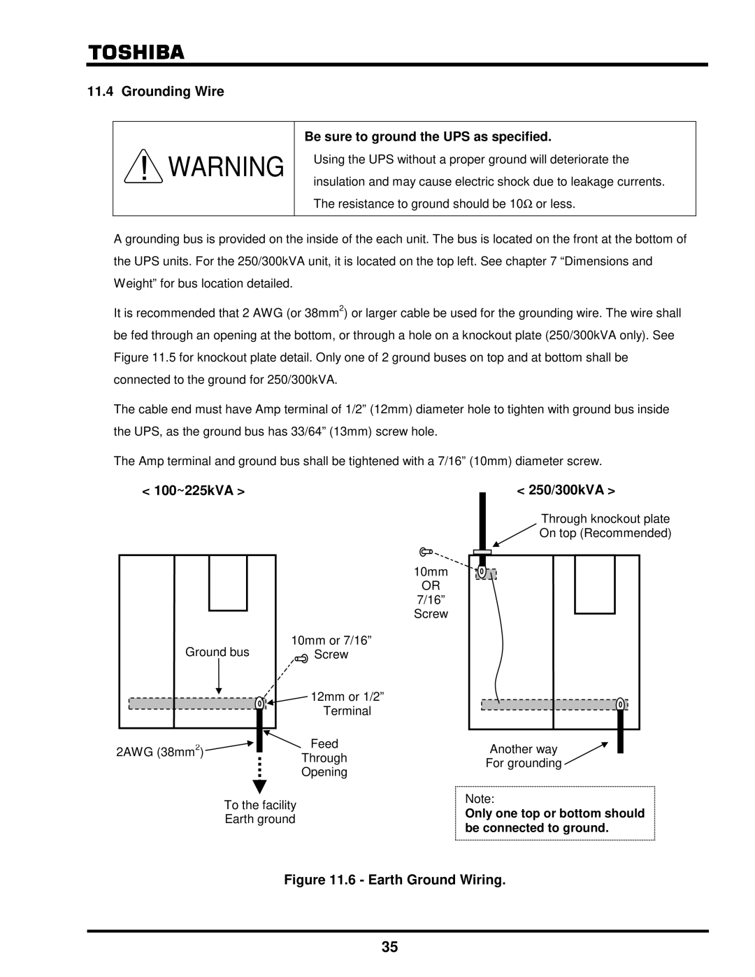
It is recommended that 2 AWG (or 38mm2) or larger cable be used for the grounding wire. The wire shall be fed through an opening at the bottom, or through a hole on a knockout plate (250/300kVA only). See Figure 11.5 for knockout plate detail. Only one of 2 ground buses on top and at bottom shall be connected to the ground for 250/300kVA.
The cable end must have Amp terminal of 1/2” (12mm) diameter hole to tighten with ground bus inside the UPS, as the ground bus has 33/64” (13mm) screw hole.
The Amp terminal and ground bus shall be tightened with a 7/16” (10mm) diameter screw.
< 100~225kVA > |
| < 250/300kVA > |
|
| Through knockout plate |
|
| On top (Recommended) |
|
| 10mm |
|
| OR |
|
| 7/16” |
|
| Screw |
Ground bus | 10mm or 7/16” |
|
Screw |
| |
| 12mm or 1/2” |
|
| Terminal |
|
2AWG (38mm2) | Feed | Another way |
| Through | For grounding |
| Opening | |
|
|
To the facility Earth ground
Note:
Only one top or bottom should be connected to ground.
Figure 11.6 - Earth Ground Wiring.
35