Manuals
/
Brands
/
Computer Equipment
/
Power Supply
/
Toshiba
/
Computer Equipment
/
Power Supply
Toshiba
G8000 Series
Figure 7.3 - 250/300kVA UPS Exterior dimensions (front & right side).
1
20
41
41
Download
41 pages, 1.01 Mb
19
(76.8”)
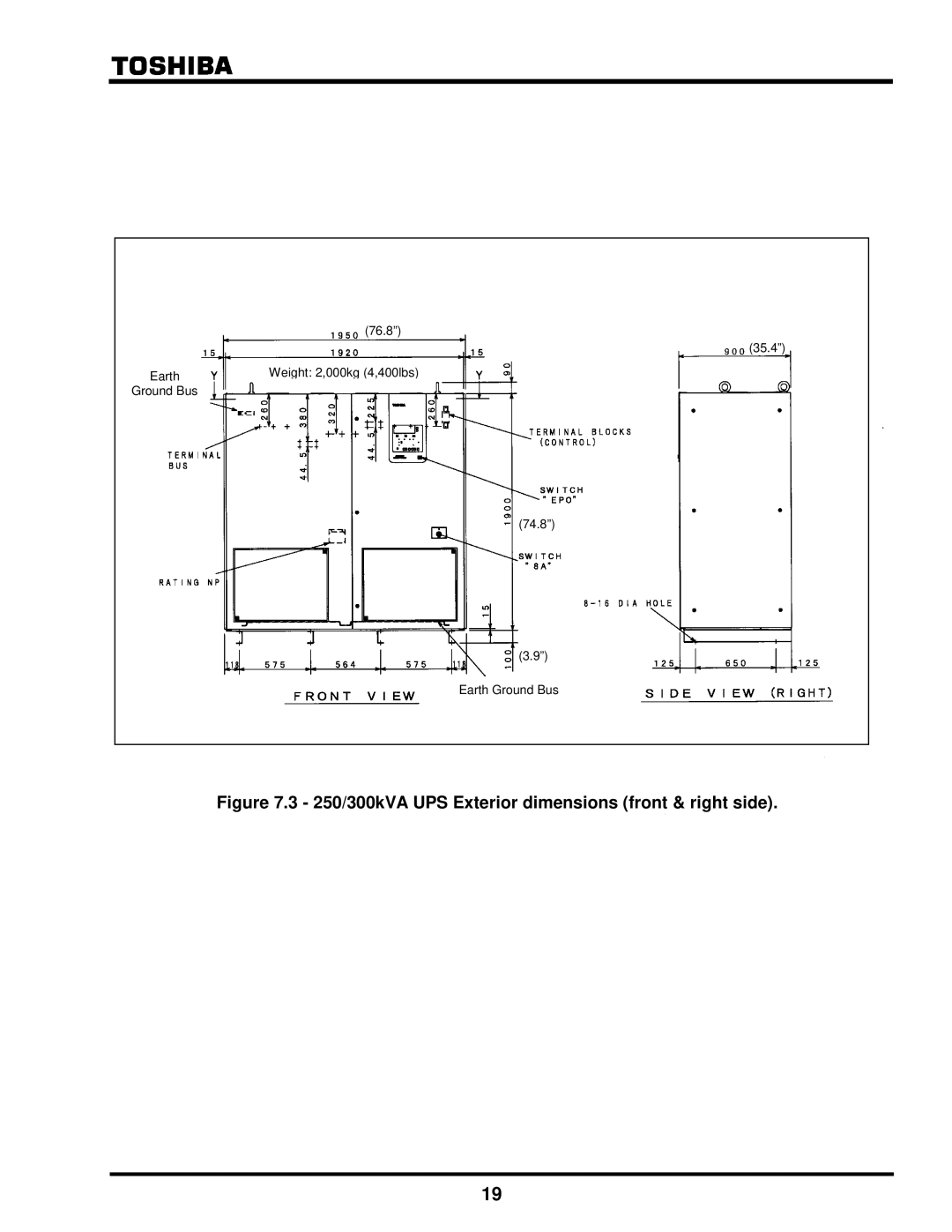
Weight: 2,000kg (4,400lbs)
Earth
Ground Bus
Earth Ground Bus
(74.8”)
(3.9”)
(35.4”)
Figure 7.3 - 250/300kVA UPS Exterior dimensions (front & right side).
Contents
Main
1. Introduction
Notice
2
UNINTERRUPTIBLE POWER SUPPLY
Manuals Purpose and Scope
Contacting Toshibas Customer Support Center
2. General Safety Instructions
3. IMPORTANT SAFETY INSTRUCTIONS
SAVE THESE INSTRUCTIONS
CAUTION
4. Safety Precautions
Page
5. Installation Precautions
Installation Environment
The UPS is to be installed in a controlled environment.
Page
Page
Page
Page
14
WARNING
15
Grounding Electrode Terminal
CAUTION
6. Contents
7. Dimensions and Weight
Figure 7.2 - 150/180/225kVA UPS Exterior dimensions (front & right side).
Figure 7.3 - 250/300kVA UPS Exterior dimensions (front & right side).
8. Transportation
Page
Page
9. Storage
10. Installation
Tighten anchor bolts to secure the UPS to the installation floor.
Ensure that there is adequate working space
Page
10.3 Anchor bolts
Anchor Bolt
) screw holes
(5/8
Figure 10.3 - Hole locations and dimensions for anchor bolts.
11. Wiring
11.1 Overview
Figure 11.1 - External Wiring Diagram.
Page
Page
Page
Page
Page
Page
11.3 External Breakers
Table 11.9 External Breaker Rating.
11.4 Grounding Wire
Figure 11.6 - Earth Ground Wiring.
< 250/300kVA >
< 100~225kVA >
11.5 Control Wires
.
11.6 Grounding configuration
11.6.1 Recommended configuration with input neutral grounded
Figure 11.8 - Grounding configuration with input neutral grounded.
Figure 11.9 - Jumper cable between the neutral terminal & ground bus.
11.6.2 Grounding configuration without input neutral
Figure 11.10 - Grounding configuration without input neutral.
11.6.3 Recommended configuration with delta-input
Figure 11.11 - Grounding configuration with non-grounded delta-input.
11.6.4 Grounding configuration with corner-grounded delta-input
Figure 11.12 - Grounding configuration with corner-grounded delta-input.