11.5 Control Wires
The terminal layout of control wires at TB1 is shown in Table 11.10.
Table 11.10 External Connections
No. | I/O | Signal Name | Operation |
1 | Output | Low Battery | Close at Low Battery |
2 | Output | Backup Operation | Close while Backup Operation |
3 | Output | Fault | Close by Faults |
4 | Output | Inverter Supply | Close during Normal Operation |
5 | Output | Warning | Close by Warnings |
6 | Input | P24 |
|
7 | Input | Remote Run | Close to run UPS |
8 | Input | P24 |
|
9 | Input | Remote Stop | Close to stop UPS |
10 | Output | Bypass Supply | Close during Bypass Operation |
11 | Output | Output Signal Ground | (Ground for pin #1~5 & #10) |
12 | Input | P24 | Battery’s |
13 | Input | Battery Overheat | Overheat |
14 | Output |
| Bypass Breaker |
15 | Output | 52C Trip Signal | Shunt Trip Signal by EPO |
16 | Output |
| Battery Breaker shunt trip |
17 | Output | 72B Trip Signal | by EPO or Battery shutdown |
18 | Output |
| Battery breaker’s |
19 | Output | 72B Aux. Contact | Auxiliary |
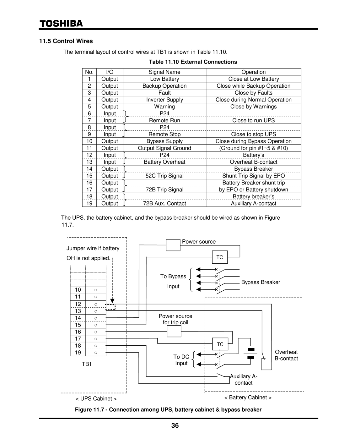
The UPS, the battery cabinet, and the bypass breaker should be wired as shown in Figure 11.7.
Jumper wire if battery
Power source
OH is not applied. |
| TC |
|
| |
|
|
| |||
|
|
|
|
|
|
|
|
|
|
|
|
|
| To Bypass | Bypass Breaker |
|
| Input | |
10 |
|
| |
|
|
| |
11 |
|
|
|
12 |
|
|
|
13 |
| Power source |
|
14 |
|
| |
| for trip coil |
| |
15 |
|
| |
|
|
| |
16 |
|
|
|
17 |
|
| TC |
18 |
|
| |
19 | ○ | To DC | Overheat |
|
| ||
| TB1 | Input |
|
|
|
| Auxiliary A- |
|
|
| contact |
< UPS Cabinet > |
| < Battery Cabinet > | |
Figure 11.7 - Connection among UPS, battery cabinet & bypass breaker
36