11.6 Grounding configuration
This section describes the grounding configuration with AC input service entrance.
As inadequate grounding configuration causes problems on
11.6.1 Recommended configuration with input neutral grounded
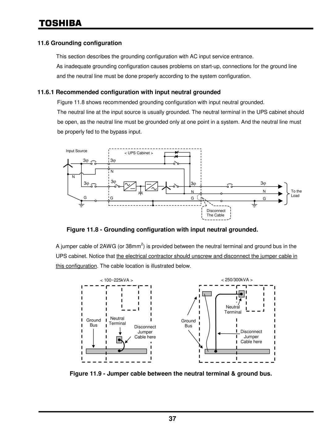
Figure 11.8 shows recommended grounding configuration with input neutral grounded.
The neutral line at the input source is usually grounded. The neutral terminal in the UPS cabinet should be open, as the neutral line must be grounded only at one point in a system. And the neutral line must be properly fed to the bypass input.
Input Source
3
N
3
G
| < UPS Cabinet > |
3 |
|
N |
|
3 | 3 |
| |
| N |
G | G |
3
|
|
|
|
| N |
|
| To the |
|
|
|
|
| G |
|
| Load |
|
|
|
|
|
|
|
| |
|
|
|
|
|
|
|
|
|
Disconnect
The Cable
Figure 11.8 - Grounding configuration with input neutral grounded.
A jumper cable of 2AWG (or 38mm2) is provided between the neutral terminal and ground bus in the UPS cabinet. Notice that the electrical contractor should unscrew and disconnect the jumper cable in this configuration. The cable location is illustrated below.
| < 100~225kVA > |
| |
Ground | Neutral |
| |
Terminal |
| ||
Bus |
| Disconnect | |
|
| ||
|
|
| |
|
|
| Jumper |
|
|
| Cable here |
< 250/300kVA > |
Neutral |
Terminal |
Ground |
Bus |
Disconnect |
Jumper |
Cable here |
Figure 11.9 - Jumper cable between the neutral terminal & ground bus.
37