Table 13. Memory Box Card Connectors
Board Location | Connector | Description |
|
|
|
C8 | JD2A0 | |
|
|
|
C9 | VHDM |
|
|
|
|
DIMM Configurations
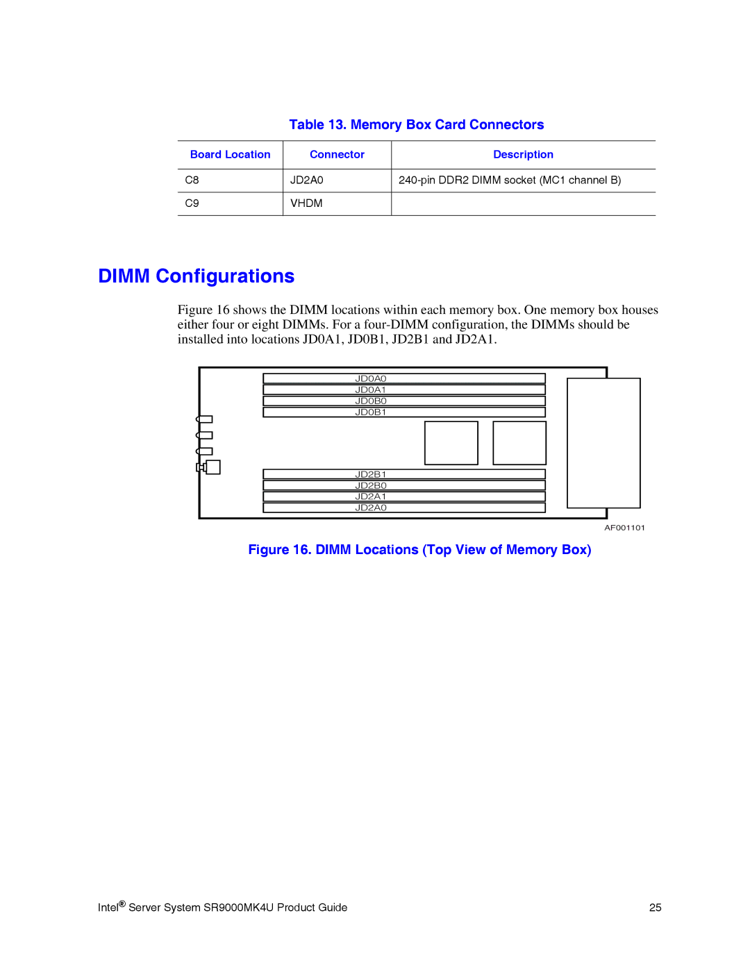
Figure 16 shows the DIMM locations within each memory box. One memory box houses either four or eight DIMMs. For a four-DIMM configuration, the DIMMs should be installed into locations JD0A1, JD0B1, JD2B1 and JD2A1.
JD0A0
JD0A1
JD0B0
JD0B1
JD2B1
JD2B0
JD2A1
JD2A0
AF001101
Figure 16. DIMM Locations (Top View of Memory Box)
Intel® Server System SR9000MK4U Product Guide | 25 |