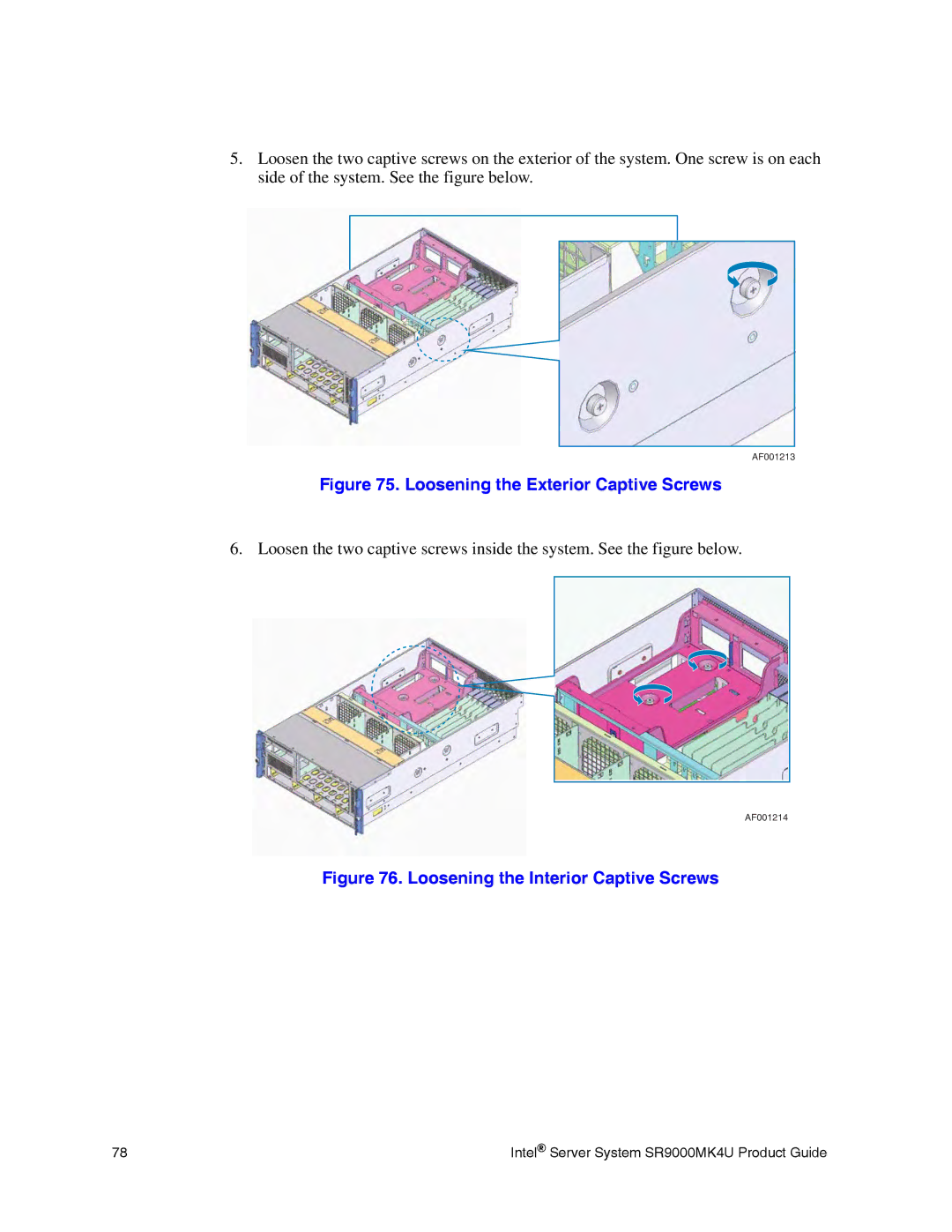
5.Loosen the two captive screws on the exterior of the system. One screw is on each side of the system. See the figure below.
AF001213
Figure 75. Loosening the Exterior Captive Screws
6. Loosen the two captive screws inside the system. See the figure below.
AF001214
Figure 76. Loosening the Interior Captive Screws
78 | Intel® Server System SR9000MK4U Product Guide |
