Chassis Front
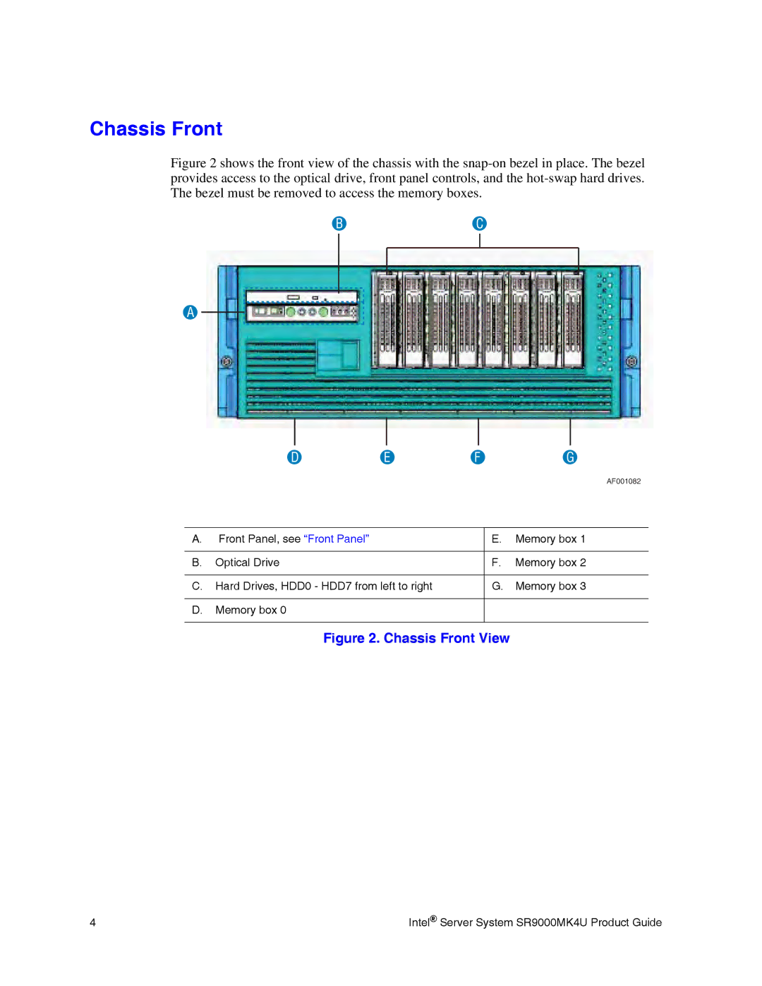
Figure 2 shows the front view of the chassis with the snap-on bezel in place. The bezel provides access to the optical drive, front panel controls, and the hot-swap hard drives. The bezel must be removed to access the memory boxes.
BC
A
| D | E | F | G | |
|
|
|
|
| AF001082 |
|
|
|
|
| |
A. Front Panel, see “Front Panel” |
|
| E. | Memory box 1 | |
|
|
|
|
|
|
B. | Optical Drive |
|
| F. | Memory box 2 |
|
|
|
| ||
C. Hard Drives, HDD0 - HDD7 from left to right |
| G. | Memory box 3 | ||
|
|
|
|
|
|
D. | Memory box 0 |
|
|
|
|
|
|
|
|
|
|
Figure 2. Chassis Front View
4 | Intel® Server System SR9000MK4U Product Guide |