Internal Layout
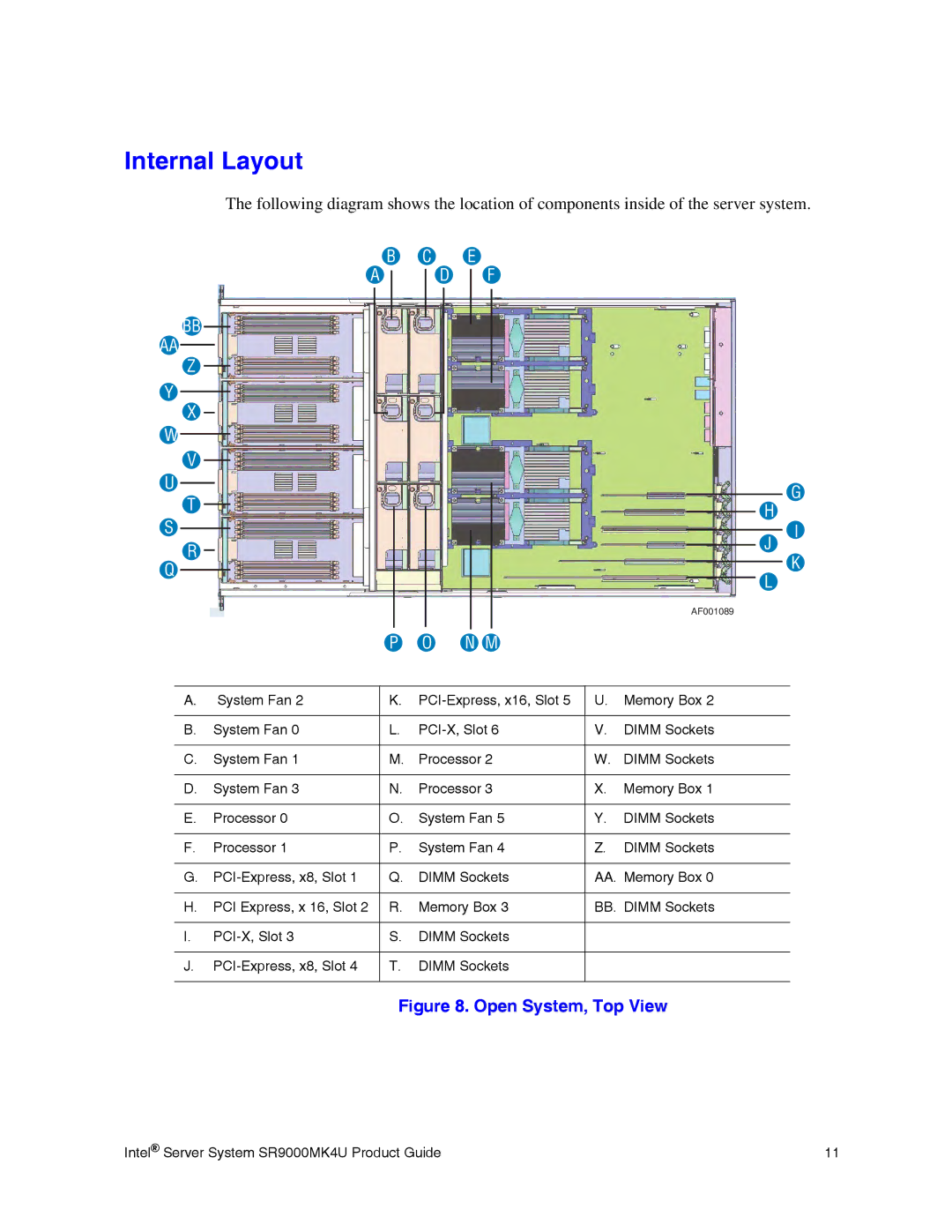
The following diagram shows the location of components inside of the server system.
B C E
A
BB
AA
Z
Y
X
W
V
U
T
D
F
G
H
S
R
J
I
Q
K
L
AF001089
|
| P | O | N M |
|
|
|
|
|
|
|
| |
A. | System Fan 2 | K. | U. | Memory Box 2 | ||
|
|
|
|
|
| |
B. | System Fan 0 | L. | V. | DIMM Sockets | ||
|
|
|
|
|
| |
C. | System Fan 1 | M. | Processor 2 | W. | DIMM Sockets | |
|
|
|
|
|
| |
D. | System Fan 3 | N. | Processor 3 | X. | Memory Box 1 | |
|
|
|
|
|
| |
E. | Processor 0 | O. | System Fan 5 | Y. | DIMM Sockets | |
|
|
|
|
|
| |
F. | Processor 1 | P. | System Fan 4 | Z. | DIMM Sockets | |
|
|
|
|
| ||
G. | Q. | DIMM Sockets | AA. Memory Box 0 | |||
|
|
|
|
| ||
H. | PCI Express, x 16, Slot 2 | R. | Memory Box 3 | BB. DIMM Sockets | ||
|
|
|
|
|
| |
I. | S. | DIMM Sockets |
|
| ||
|
|
|
|
|
| |
J. | T. | DIMM Sockets |
|
| ||
|
|
|
|
|
|
|
Figure 8. Open System, Top View
Intel® Server System SR9000MK4U Product Guide | 11 |