2Intel® Server System SR9000MK4U Board Set Overview
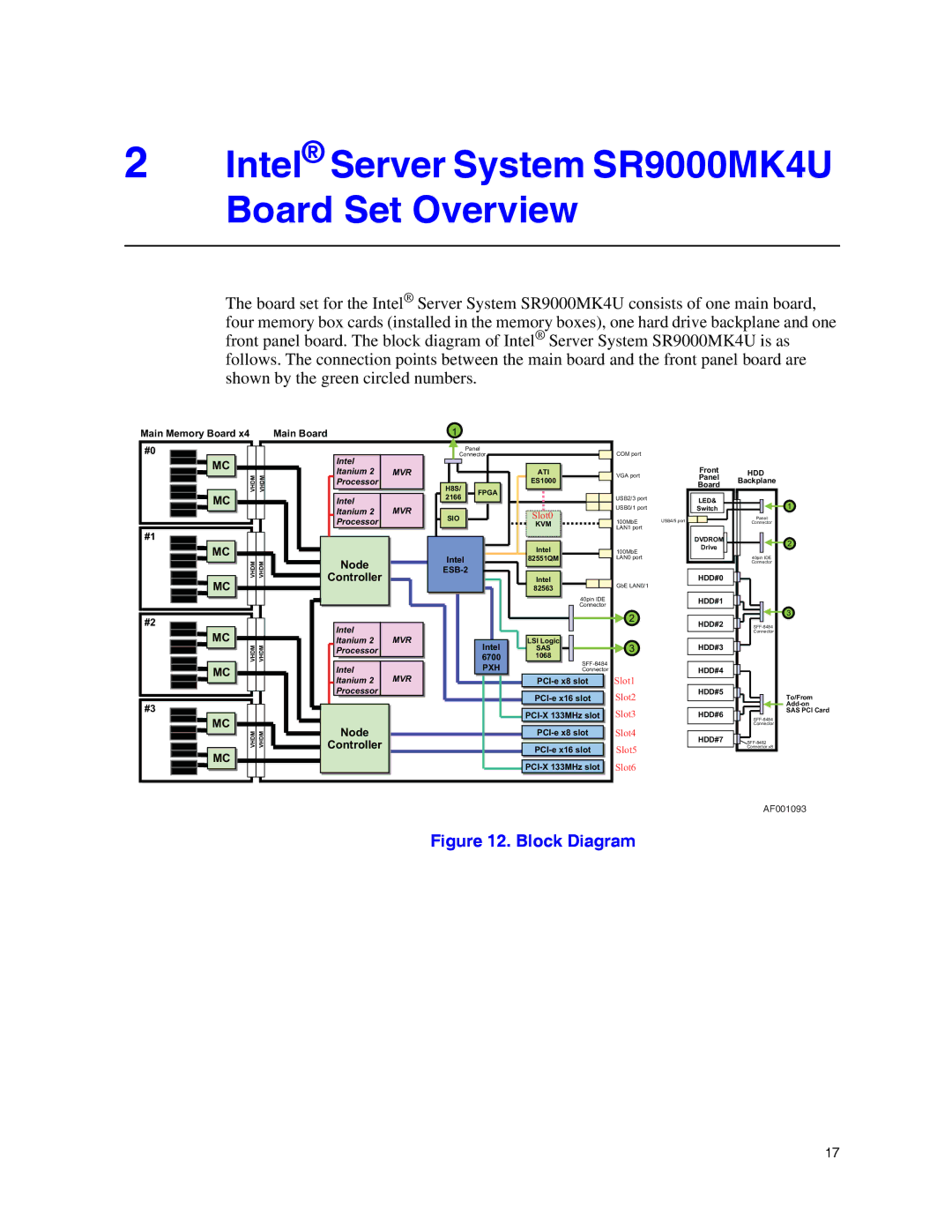
The board set for the Intel® Server System SR9000MK4U consists of one main board, four memory box cards (installed in the memory boxes), one hard drive backplane and one front panel board. The block diagram of Intel® Server System SR9000MK4U is as follows. The connection points between the main board and the front panel board are shown by the green circled numbers.
Main Memory Board x4
Main Board | 1 |
#0
![]()
![]() MC
MC ![]()
![]() VHDM VHDM
VHDM VHDM ![]() MC
MC
#1
![]()
![]() MC
MC ![]()
![]() VHDM VHDM
VHDM VHDM ![]() MC
MC
#2
![]() MC
MC ![]()
![]() VHDM VHDM
VHDM VHDM
![]() MC
MC
#3
![]() MC
MC ![]()
![]() VHDM VHDM
VHDM VHDM
![]() MC
MC
Intel |
|
Itanium 2 | MVRVR |
Itanium2 | |
Processor |
|
Intel | MVRVR |
ItaniumItanium22 | |
Processor |
|
Nodeode
Controllerontr ller
Intel | MVRVR |
ItaniumItanium22 | |
Processor |
|
Intel | MVRVR |
ItaniumItanium22 | |
Processor |
|
Nodeode
Controllerontr ller
| Panel |
| COM port |
|
Connector |
|
| ||
|
| ATI | VGA port |
|
|
| ATI |
| |
H8S/H8S/ |
| ES1000ES1000 |
|
|
FPGAFPGA |
|
|
| |
21662166 |
| USB2/3 port |
| |
|
|
| ||
|
| Slot0 | USB0/1 port |
|
SIO |
| 100MbE | USB4/5 port | |
SIO |
| KVM | ||
|
| KVM | LAN1 port |
|
|
|
|
|
|
|
|
| IntelIntel |
|
|
| 100MbE | |
| IntelIntel |
|
|
|
| 82551QM82551QM |
|
|
|
| LAN0 port | ||
|
|
|
|
|
|
|
|
| |||||
|
|
|
| IntelIntel |
|
|
|
| GbE LAN0/1 | ||||
|
|
|
|
|
|
|
| 8256382563 |
|
|
|
| |
|
|
|
|
|
|
|
|
|
| 40pin IDE |
| ||
|
|
|
|
|
|
|
|
|
|
| |||
|
|
|
|
|
|
|
|
|
| Connector | 2 | ||
|
|
|
|
|
|
|
|
|
|
|
|
| |
|
|
|
|
|
|
|
|
|
|
|
|
| |
|
|
|
|
|
|
|
|
|
|
|
| ||
|
|
|
|
|
|
|
| LSILSILogicLogic |
|
|
| ||
|
|
|
| Intel |
| SAS |
|
|
| ||||
|
|
|
| Intel |
| SAS |
|
| 3 | ||||
|
|
| 67006700 |
| 10681068 |
|
| ||||||
|
|
|
| PXHPXH |
|
|
| Connector | Slot1 | ||||
|
|
|
|
|
|
|
|
| |||||
|
|
|
|
|
|
|
|
|
|
|
|
| Slot2 |
|
|
|
|
|
|
|
|
|
|
|
|
| |
|
|
|
|
|
|
|
|
| |||||
|
|
|
|
|
|
|
|
|
|
|
|
| Slot3 |
|
|
|
|
|
|
|
|
|
|
| |||
|
|
|
|
|
|
|
|
| |||||
|
|
|
|
|
|
|
| ||||||
|
|
|
|
|
|
|
|
|
|
|
|
| Slot4 |
|
|
|
|
|
|
|
|
| |||||
|
|
|
|
|
|
|
|
|
|
|
|
| Slot5 |
|
|
|
|
|
|
|
|
| |||||
|
|
|
|
|
|
|
|
|
|
|
| Slot6 | |
|
|
|
|
|
|
|
|
| |||||
|
|
|
|
|
|
|
| ||||||
|
|
|
|
|
|
|
|
|
|
|
|
|
|
Front
Panel
Board
LED&
Switch
DVDROM
Drive
HDD#0
HDD#1
HDD#2
HDD#3
HDD#4
HDD#5
HDD#6
HDD#7
HDD
Backplane
Panel
Connector
40pin IDE Connector
Connector
Connector
![]() SFF-8482
SFF-8482
1
2
3
To/From
SAS PCI Card
AF001093
Figure 12. Block Diagram
17
