11.Carefully set the processor assembly into place on the main board, aligning the heatsink screws with the corresponding holes in the server board. See the figure below.
Caution: Do not allow the processor pins to rub against the processor socket. If the processor does not seated easily, remove the assembly, inspect pins, socket and heat sink for possible damage, and set the assembly into place again.
AF001268
Figure 116. Setting the Processor Assembly into Place over the Processor
Socket
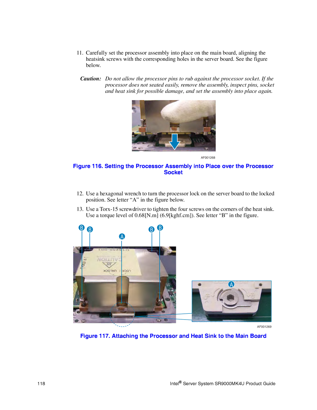
12.Use a hexagonal wrench to turn the processor lock on the server board to the locked position. See letter “A” in the figure below.
13.Use a
B BB B
A
A
AF001269
Figure 117. Attaching the Processor and Heat Sink to the Main Board
118 | Intel® Server System SR9000MK4U Product Guide |