Memory Box Card
|
| c4 |
|
| c3 |
|
| c2 |
|
| c1 |
Mirror LED |
| P3 |
| ||
Power LED |
| P4 |
| ||
|
Attention LED ![]()
![]() P5
P5
Hot Swap SW ![]()
![]()
![]() P6
P6
c5
c6
c7
c8
JD0A0
JD0A1
JD0B0
JD0B1
P2 |
| P1 |
|
| MC2 |
| MC0 |
|
|
|
|
JD2B1
JD2B0
JD2A1
JD2A0
c9
VHDM
AF001096
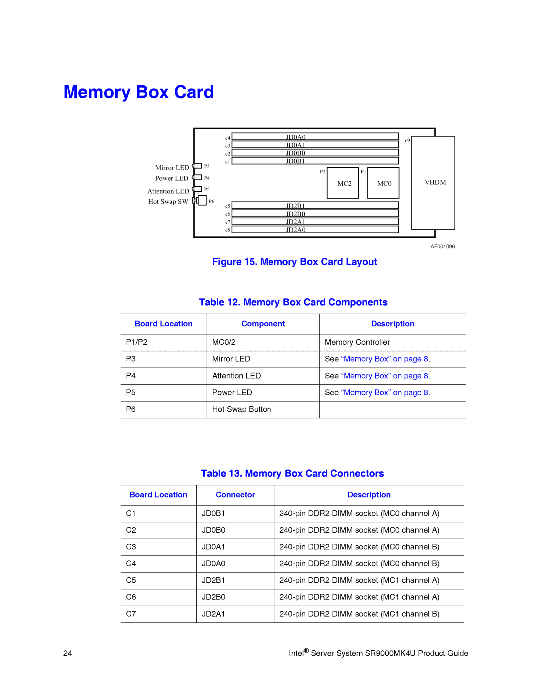
Figure 15. Memory Box Card Layout
Table 12. Memory Box Card Components
Board Location | Component | Description |
|
|
|
P1/P2 | MC0/2 | Memory Controller |
|
|
|
P3 | Mirror LED | See “Memory Box” on page 8. |
|
|
|
P4 | Attention LED | See “Memory Box” on page 8. |
|
|
|
P5 | Power LED | See “Memory Box” on page 8. |
|
|
|
P6 | Hot Swap Button |
|
|
|
|
Table 13. Memory Box Card Connectors
Board Location | Connector | Description |
|
|
|
C1 | JD0B1 | |
|
|
|
C2 | JD0B0 | |
|
|
|
C3 | JD0A1 | |
|
|
|
C4 | JD0A0 | |
|
|
|
C5 | JD2B1 | |
|
|
|
C6 | JD2B0 | |
|
|
|
C7 | JD2A1 | |
|
|
|
24 | Intel® Server System SR9000MK4U Product Guide |