Cable Connections
A B
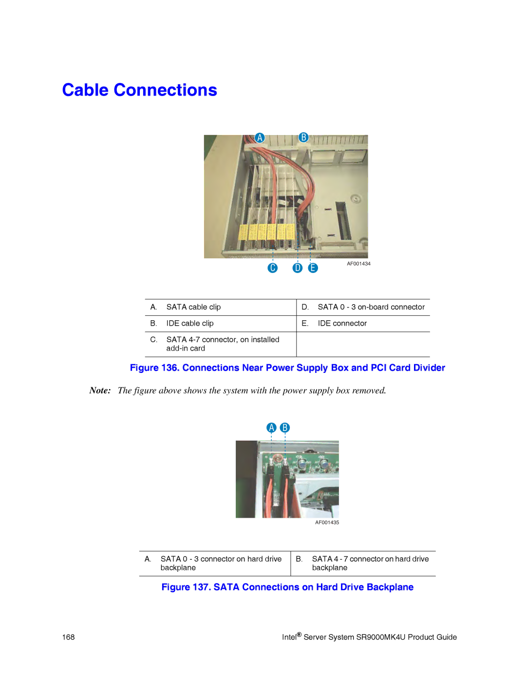
| C | D | E | AF001434 |
|
| |||
|
|
| ||
A. | SATA cable clip | D. SATA 0 - 3 | ||
|
|
|
|
|
B. | IDE cable clip | E. |
| IDE connector |
C.SATA
Figure 136. Connections Near Power Supply Box and PCI Card Divider
Note: The figure above shows the system with the power supply box removed.
A B
AF001435
A.SATA 0 - 3 connector on hard drive backplane
B.SATA 4 - 7 connector on hard drive backplane
Figure 137. SATA Connections on Hard Drive Backplane
168 | Intel® Server System SR9000MK4U Product Guide |