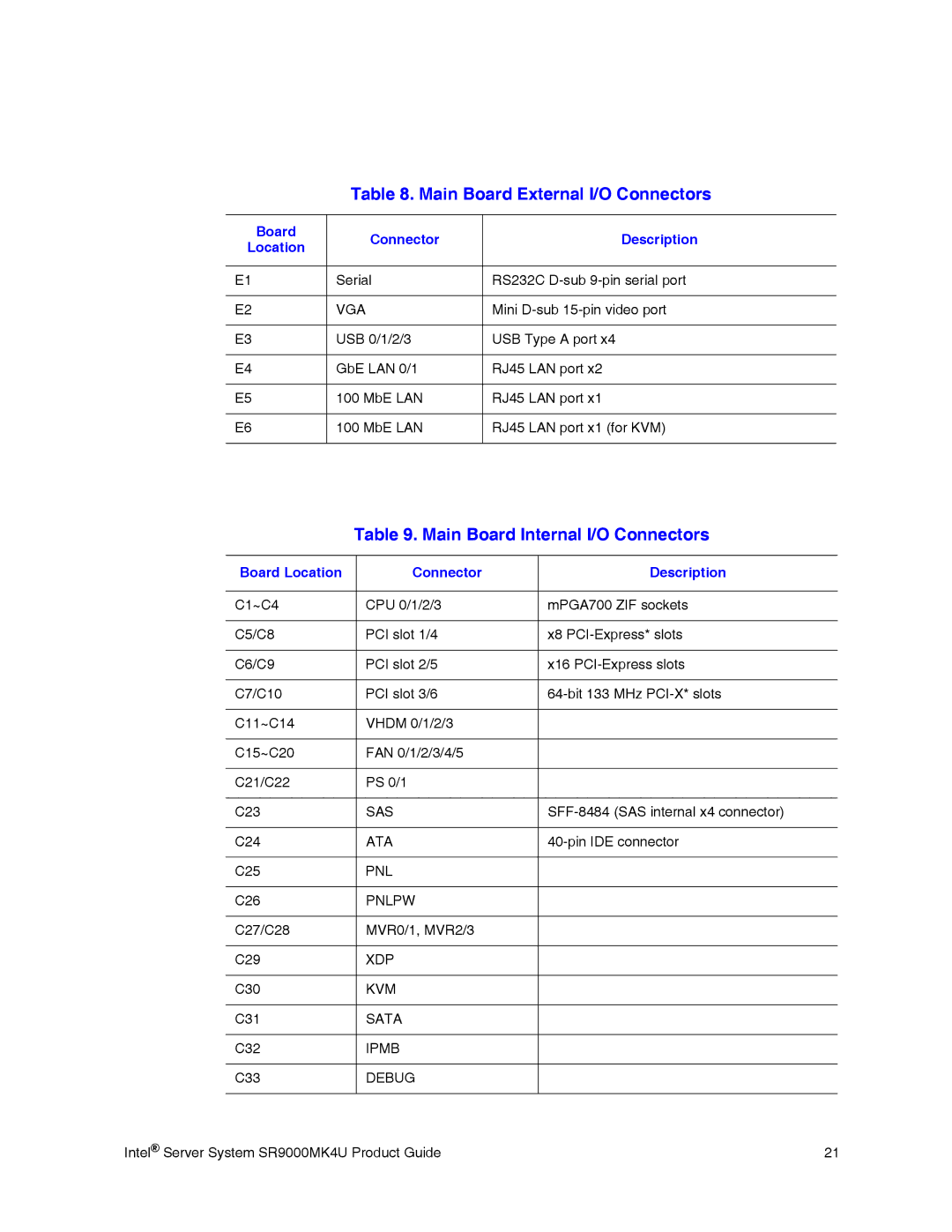
Table 8. Main Board External I/O Connectors
Board | Connector | Description | |
Location | |||
|
| ||
|
|
| |
E1 | Serial | RS232C | |
|
|
| |
E2 | VGA | Mini | |
|
|
| |
E3 | USB 0/1/2/3 | USB Type A port x4 | |
|
|
| |
E4 | GbE LAN 0/1 | RJ45 LAN port x2 | |
|
|
| |
E5 | 100 MbE LAN | RJ45 LAN port x1 | |
|
|
| |
E6 | 100 MbE LAN | RJ45 LAN port x1 (for KVM) | |
|
|
|
Table 9. Main Board Internal I/O Connectors
Board Location | Connector | Description |
|
|
|
C1~C4 | CPU 0/1/2/3 | mPGA700 ZIF sockets |
|
|
|
C5/C8 | PCI slot 1/4 | x8 |
|
|
|
C6/C9 | PCI slot 2/5 | x16 |
|
|
|
C7/C10 | PCI slot 3/6 | |
|
|
|
C11~C14 | VHDM 0/1/2/3 |
|
|
|
|
C15~C20 | FAN 0/1/2/3/4/5 |
|
|
|
|
C21/C22 | PS 0/1 |
|
|
|
|
C23 | SAS | |
|
|
|
C24 | ATA | |
|
|
|
C25 | PNL |
|
|
|
|
C26 | PNLPW |
|
|
|
|
C27/C28 | MVR0/1, MVR2/3 |
|
|
|
|
C29 | XDP |
|
|
|
|
C30 | KVM |
|
|
|
|
C31 | SATA |
|
|
|
|
C32 | IPMB |
|
|
|
|
C33 | DEBUG |
|
|
|
|
Intel® Server System SR9000MK4U Product Guide | 21 |