A
AF001436
BB
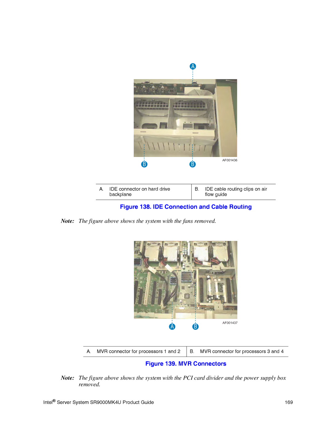
A.IDE connector on hard drive backplane
B.IDE cable routing clips on air flow guide
Figure 138. IDE Connection and Cable Routing
Note: The figure above shows the system with the fans removed.
AF001437
A B
A.MVR connector for processors 1 and 2
B.MVR connector for processors 3 and 4
Figure 139. MVR Connectors
Note: The figure above shows the system with the PCI card divider and the power supply box removed.
Intel® Server System SR9000MK4U Product Guide | 169 |