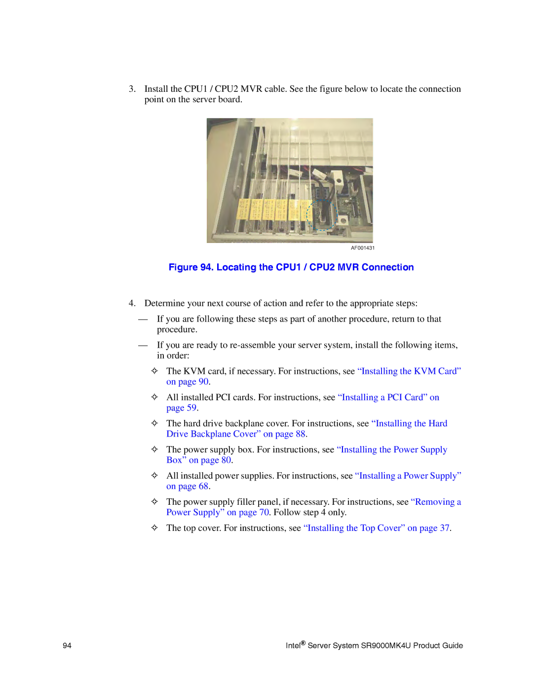
3.Install the CPU1 / CPU2 MVR cable. See the figure below to locate the connection point on the server board.
AF001431
Figure 94. Locating the CPU1 / CPU2 MVR Connection
4.Determine your next course of action and refer to the appropriate steps:
—If you are following these steps as part of another procedure, return to that procedure.
—If you are ready to
✧The KVM card, if necessary. For instructions, see “Installing the KVM Card” on page 90.
✧All installed PCI cards. For instructions, see “Installing a PCI Card” on page 59.
✧The hard drive backplane cover. For instructions, see “Installing the Hard Drive Backplane Cover” on page 88.
✧The power supply box. For instructions, see “Installing the Power Supply Box” on page 80.
✧All installed power supplies. For instructions, see “Installing a Power Supply” on page 68.
✧The power supply filler panel, if necessary. For instructions, see “Removing a Power Supply” on page 70. Follow step 4 only.
✧The top cover. For instructions, see “Installing the Top Cover” on page 37.
94 | Intel® Server System SR9000MK4U Product Guide |