Chassis Rear
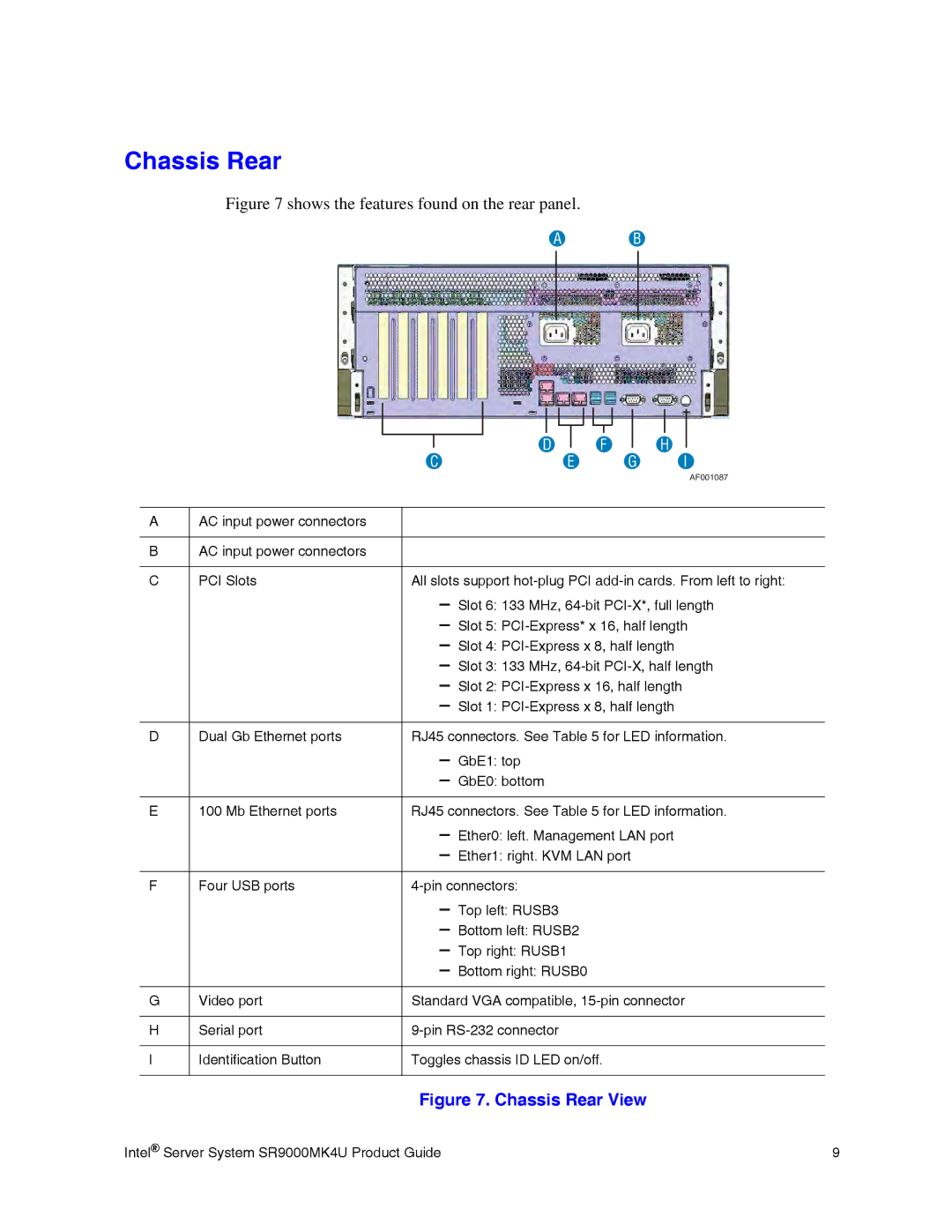
Figure 7 shows the features found on the rear panel.
A B
|
|
|
|
|
|
|
|
|
|
|
|
|
|
|
|
|
|
|
|
|
|
|
|
|
|
|
|
|
|
|
|
|
|
|
|
|
|
|
|
|
|
|
|
|
|
|
|
|
|
|
|
|
|
|
|
|
|
|
|
|
|
|
|
|
|
|
|
| D |
|
| F |
|
| H |
|
| ||||||
|
|
|
|
|
|
|
| |||||||||||||
|
|
| C |
|
|
| E |
|
| G |
| I | ||||||||
|
|
|
|
|
|
|
|
|
|
|
|
|
|
|
|
|
|
|
| AF001087 |
|
|
|
|
|
|
|
|
|
|
|
|
|
|
|
|
|
|
|
|
|
A | AC input power connectors |
|
|
|
|
|
|
|
|
|
|
|
|
|
|
|
|
|
| |
|
|
|
|
|
|
|
|
|
|
|
|
|
|
|
|
|
|
|
|
|
B | AC input power connectors |
|
|
|
|
|
|
|
|
|
|
|
|
|
|
|
|
|
| |
|
|
|
|
|
| |||||||||||||||
C | PCI Slots | All slots support | ||||||||||||||||||
|
|
|
|
| – Slot 6: 133 MHz, | |||||||||||||||
|
|
|
|
| – Slot 5: | |||||||||||||||
|
|
|
|
| – Slot 4: | |||||||||||||||
|
|
|
|
| – Slot 3: 133 MHz, | |||||||||||||||
|
|
|
|
| – Slot 2: | |||||||||||||||
|
|
|
|
| – Slot 1: | |||||||||||||||
|
|
|
|
|
| |||||||||||||||
D | Dual Gb Ethernet ports | RJ45 connectors. See Table 5 for LED information. | ||||||||||||||||||
|
|
|
|
| – GbE1: top |
|
|
|
|
|
|
|
|
| ||||||
|
|
|
|
| – GbE0: bottom |
|
|
|
|
|
|
|
|
| ||||||
|
|
|
|
|
| |||||||||||||||
E | 100 Mb Ethernet ports | RJ45 connectors. See Table 5 for LED information. | ||||||||||||||||||
|
|
|
|
| – Ether0: left. Management LAN port | |||||||||||||||
|
|
|
|
| – Ether1: right. KVM LAN port |
|
|
|
| |||||||||||
|
|
|
|
|
|
|
|
|
|
|
|
|
|
| ||||||
F | Four USB ports |
|
|
|
|
|
|
|
|
| ||||||||||
|
|
|
|
| – Top left: RUSB3 |
|
|
|
|
|
|
|
|
| ||||||
|
|
|
|
| – Bottom left: RUSB2 |
|
|
|
|
|
|
|
|
| ||||||
|
|
|
|
| – Top right: RUSB1 |
|
|
|
|
|
|
|
|
| ||||||
|
|
|
|
| – Bottom right: RUSB0 |
|
|
|
|
|
|
|
|
| ||||||
|
|
|
|
|
| |||||||||||||||
G | Video port | Standard VGA compatible, | ||||||||||||||||||
|
|
|
|
|
|
|
|
|
|
|
|
|
|
| ||||||
H | Serial port |
|
|
|
|
|
|
|
|
| ||||||||||
|
|
|
|
|
|
|
|
|
| |||||||||||
I | Identification Button | Toggles chassis ID LED on/off. |
|
|
|
| ||||||||||||||
|
|
|
|
|
|
|
|
|
|
|
|
|
|
|
|
|
|
|
|
|
Figure 7. Chassis Rear View
Intel® Server System SR9000MK4U Product Guide | 9 |