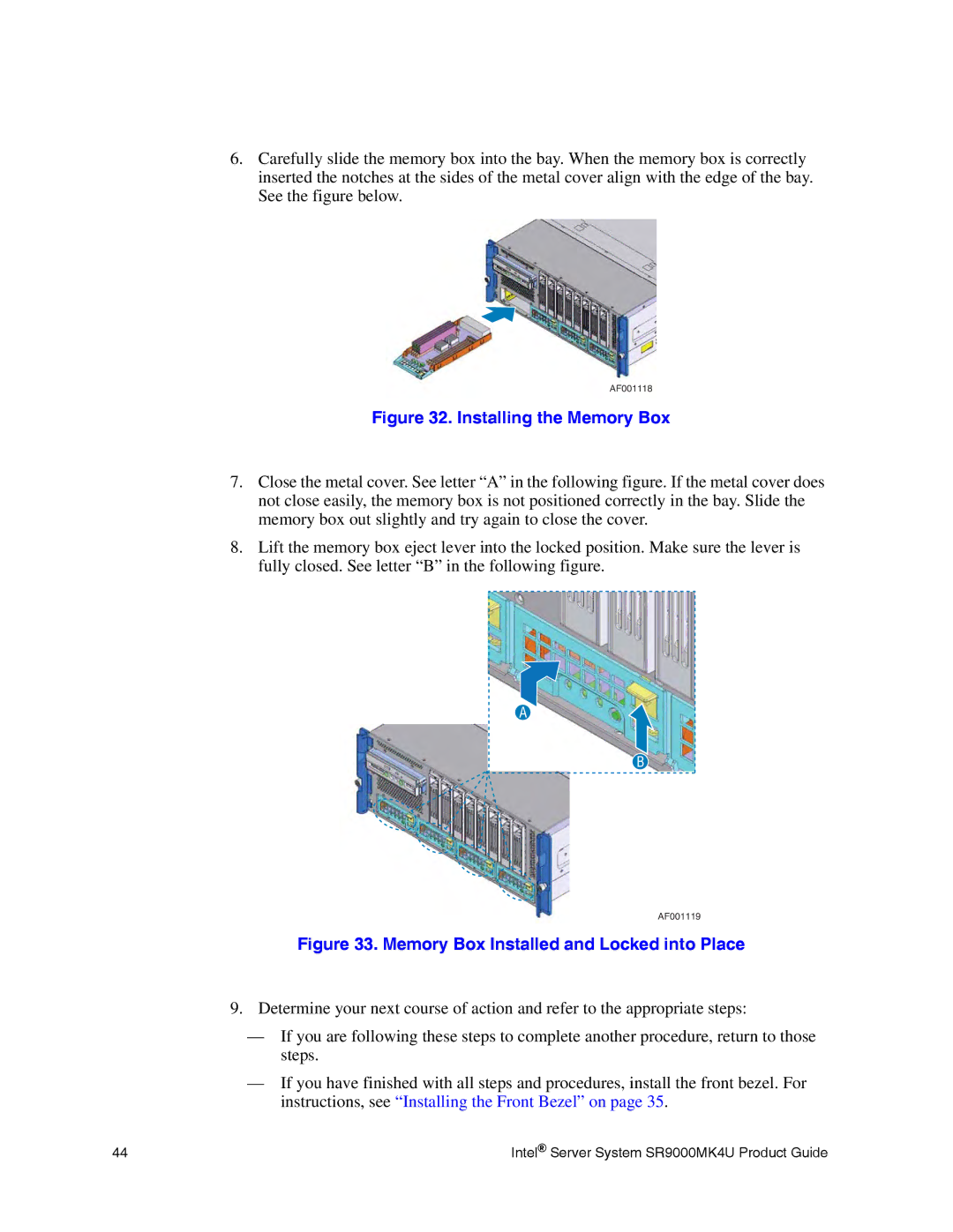
6.Carefully slide the memory box into the bay. When the memory box is correctly inserted the notches at the sides of the metal cover align with the edge of the bay. See the figure below.
AF001118
Figure 32. Installing the Memory Box
7.Close the metal cover. See letter “A” in the following figure. If the metal cover does not close easily, the memory box is not positioned correctly in the bay. Slide the memory box out slightly and try again to close the cover.
8.Lift the memory box eject lever into the locked position. Make sure the lever is fully closed. See letter “B” in the following figure.
A
B
AF001119
Figure 33. Memory Box Installed and Locked into Place
9.Determine your next course of action and refer to the appropriate steps:
—If you are following these steps to complete another procedure, return to those steps.
—If you have finished with all steps and procedures, install the front bezel. For instructions, see “Installing the Front Bezel” on page 35.
44 | Intel® Server System SR9000MK4U Product Guide |