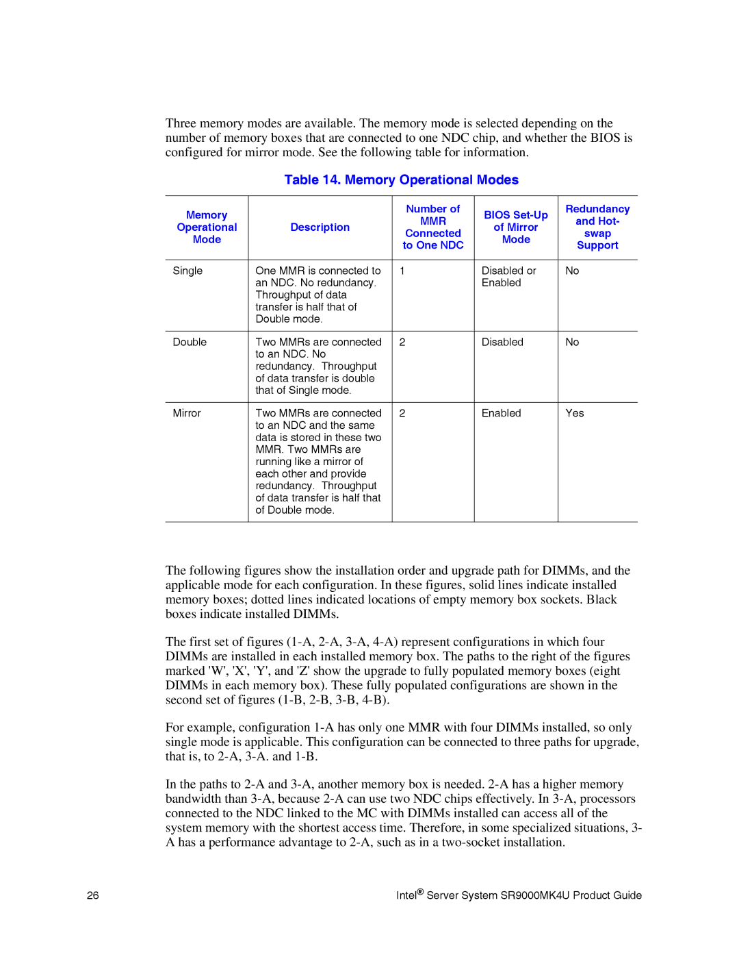
Three memory modes are available. The memory mode is selected depending on the number of memory boxes that are connected to one NDC chip, and whether the BIOS is configured for mirror mode. See the following table for information.
Table 14. Memory Operational Modes
Memory |
| Number of | BIOS | Redundancy | |
| MMR | and Hot- | |||
Operational | Description | of Mirror | |||
Connected | swap | ||||
Mode |
| Mode | |||
| to One NDC | Support | |||
|
|
| |||
|
|
|
|
| |
Single | One MMR is connected to | 1 | Disabled or | No | |
| an NDC. No redundancy. |
| Enabled |
| |
| Throughput of data |
|
|
| |
| transfer is half that of |
|
|
| |
| Double mode. |
|
|
| |
|
|
|
|
| |
Double | Two MMRs are connected | 2 | Disabled | No | |
| to an NDC. No |
|
|
| |
| redundancy. Throughput |
|
|
| |
| of data transfer is double |
|
|
| |
| that of Single mode. |
|
|
| |
|
|
|
|
| |
Mirror | Two MMRs are connected | 2 | Enabled | Yes | |
| to an NDC and the same |
|
|
| |
| data is stored in these two |
|
|
| |
| MMR. Two MMRs are |
|
|
| |
| running like a mirror of |
|
|
| |
| each other and provide |
|
|
| |
| redundancy. Throughput |
|
|
| |
| of data transfer is half that |
|
|
| |
| of Double mode. |
|
|
| |
|
|
|
|
|
The following figures show the installation order and upgrade path for DIMMs, and the applicable mode for each configuration. In these figures, solid lines indicate installed memory boxes; dotted lines indicated locations of empty memory box sockets. Black boxes indicate installed DIMMs.
The first set of figures
For example, configuration
In the paths to
26 | Intel® Server System SR9000MK4U Product Guide |