A. Connector Pin Assignments
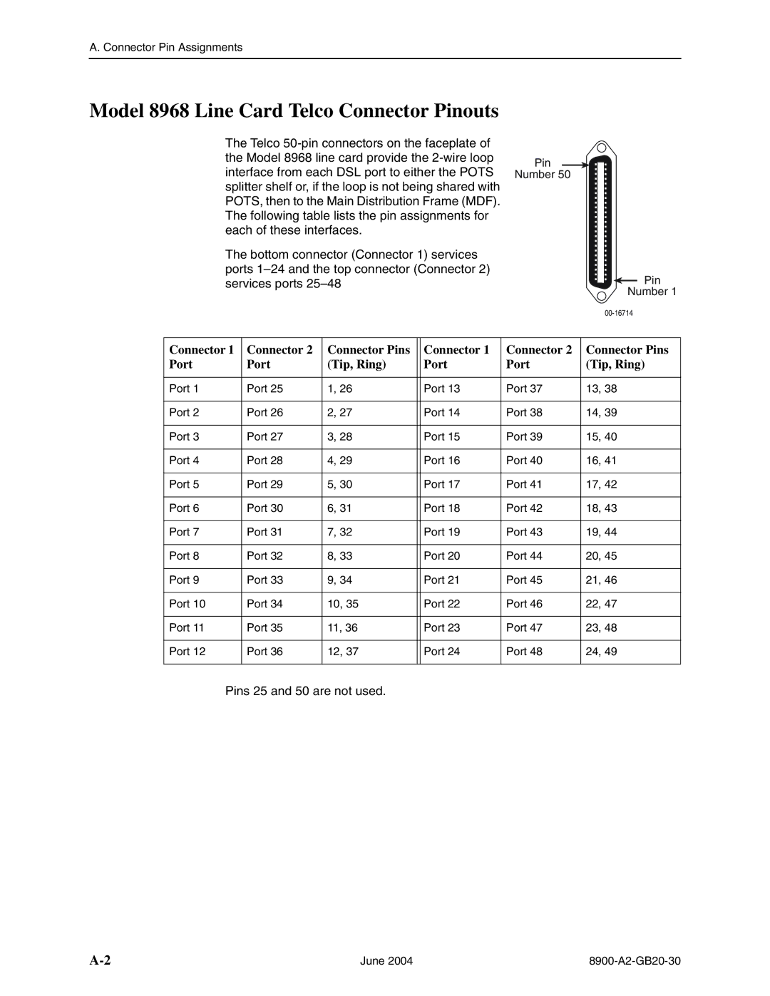
Model 8968 Line Card Telco Connector Pinouts
The Telco
The bottom connector (Connector 1) services ports
Pin
Number 50
Pin
Number 1
Connector 1 | Connector 2 | Connector Pins |
| Connector 1 | Connector 2 | Connector Pins |
Port | Port | (Tip, Ring) |
| Port | Port | (Tip, Ring) |
|
|
|
|
|
|
|
Port 1 | Port 25 | 1, 26 |
| Port 13 | Port 37 | 13, 38 |
|
|
|
|
|
|
|
Port 2 | Port 26 | 2, 27 |
| Port 14 | Port 38 | 14, 39 |
|
|
|
|
|
|
|
Port 3 | Port 27 | 3, 28 |
| Port 15 | Port 39 | 15, 40 |
|
|
|
|
|
|
|
Port 4 | Port 28 | 4, 29 |
| Port 16 | Port 40 | 16, 41 |
|
|
|
|
|
|
|
Port 5 | Port 29 | 5, 30 |
| Port 17 | Port 41 | 17, 42 |
|
|
|
|
|
|
|
Port 6 | Port 30 | 6, 31 |
| Port 18 | Port 42 | 18, 43 |
|
|
|
|
|
|
|
Port 7 | Port 31 | 7, 32 |
| Port 19 | Port 43 | 19, 44 |
|
|
|
|
|
|
|
Port 8 | Port 32 | 8, 33 |
| Port 20 | Port 44 | 20, 45 |
|
|
|
|
|
|
|
Port 9 | Port 33 | 9, 34 |
| Port 21 | Port 45 | 21, 46 |
|
|
|
|
|
|
|
Port 10 | Port 34 | 10, 35 |
| Port 22 | Port 46 | 22, 47 |
|
|
|
|
|
|
|
Port 11 | Port 35 | 11, 36 |
| Port 23 | Port 47 | 23, 48 |
|
|
|
|
|
|
|
Port 12 | Port 36 | 12, 37 |
| Port 24 | Port 48 | 24, 49 |
|
|
|
|
|
|
|
Pins 25 and 50 are not used.
June 2004 |