Cisco 6100 Series System Cables 3 |
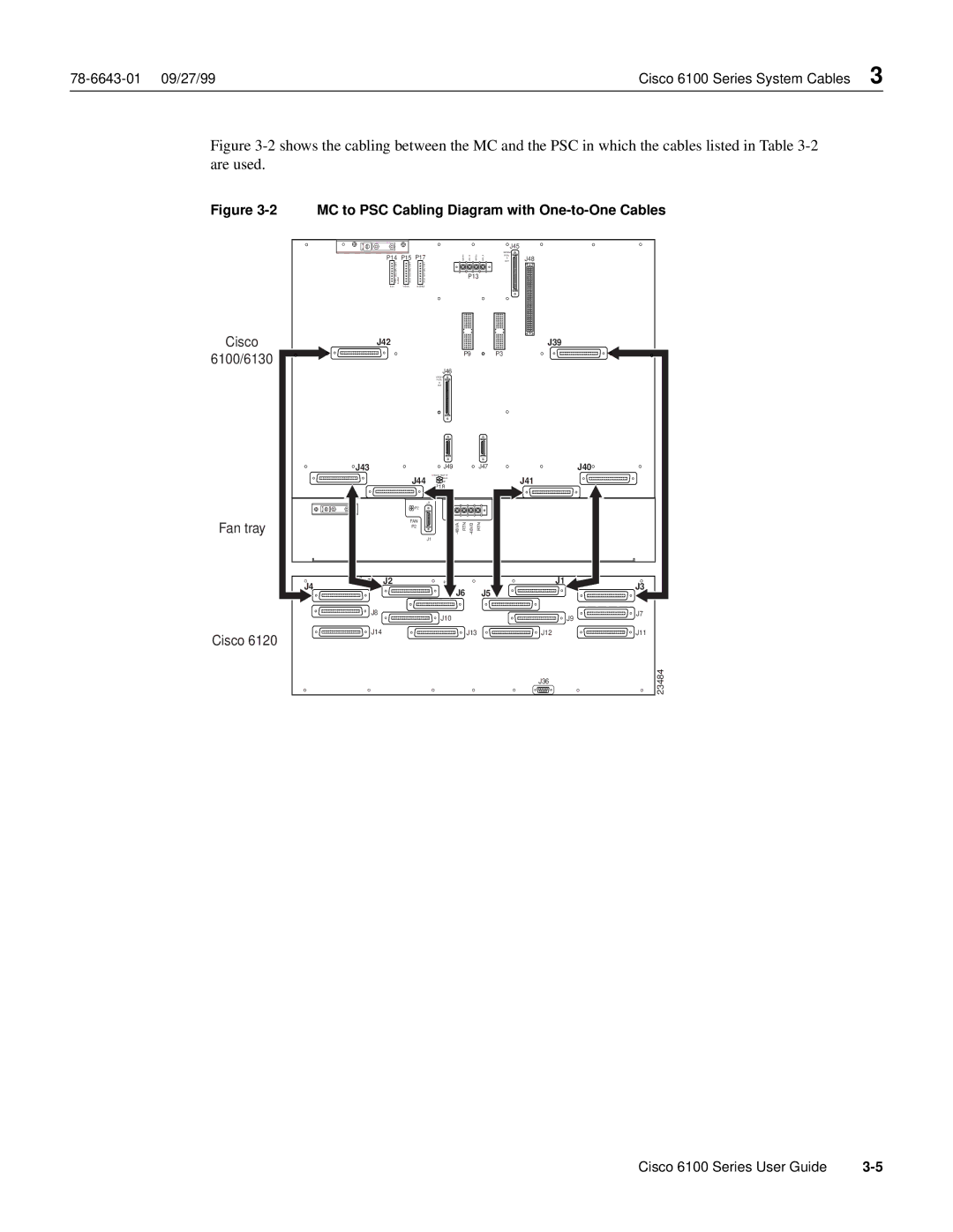
Figure 3-2 shows the cabling between the MC and the PSC in which the cables listed in Table 3-2 are used.
Figure 3-2 MC to PSC Cabling Diagram with One-to-One Cables
Cisco
6100/6130
Fan tray
Cisco 6120
|
|
|
|
|
| J45 |
|
P14 | P15 | P17 | 48RTN- | 48V- B 48RTN- | 48V- A | MODEM | J48 |
OUT | |||||||
|
|
|
|
|
| POOL |
|
|
|
|
|
|
| A |
|
CRIT | CRIT | CRIT |
|
|
|
|
|
MAJ | MAJ | MAJ |
|
|
|
|
|
MIN | MIN | MIN |
| P13 |
|
|
|
FAN ALARM | ACO | ACO |
|
|
|
| |
|
|
|
|
| |||
E2A | VISUAL | AUDIBLE |
|
|
|
|
|
J42 | J39 |
P9 | P3 |
J46
MODEM
POOL
B
OUT
J43 |
| J49 |
|
| J47 |
| J40 |
| J44 | ANALOG TEST I/F |
|
|
| J41 |
|
| RING |
|
|
|
| ||
| TIP |
|
|
|
| ||
|
|
|
|
|
| ||
|
| J1 |
|
|
|
|
|
| P2 |
|
|
|
|
|
|
| FAN | RTN | RTN |
|
| ||
| P2 |
|
| ||||
|
|
|
| ||||
|
| J1 |
|
|
|
|
|
J4 | J2 |
|
|
|
|
| J1 |
| J6 |
| J5 |
| J3 | ||
|
|
|
|
| |||
| J8 | J10 |
|
|
|
| J7 |
|
|
|
|
|
| J9 | |
| J14 |
|
| J13 |
| J12 | J11 |
|
|
|
|
|
| J36 | 23484 |
|
|
|
|
|
|
| |
Cisco 6100 Series User Guide |