Cisco 6100 Series System Cables 3 |
3.5.1 Cabling Diagrams
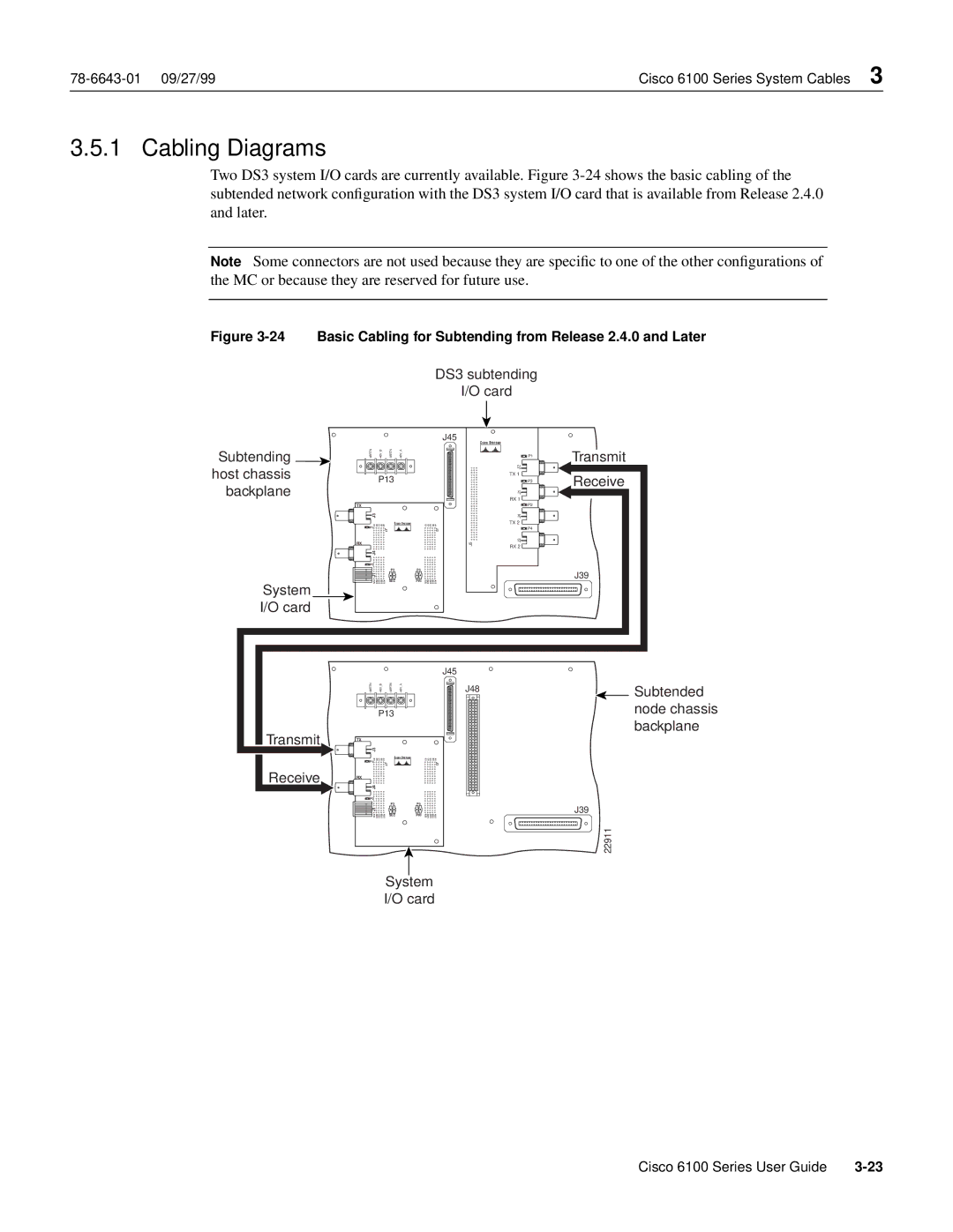
Two DS3 system I/O cards are currently available. Figure
Note Some connectors are not used because they are specific to one of the other configurations of the MC or because they are reserved for future use.
Figure 3-24 Basic Cabling for Subtending from Release 2.4.0 and Later
DS3 subtending
I/O card
Subtending ![]() host chassis
host chassis
backplane
System
I/O card
J45
48RTN |
| 48V B | 48RTN | 48V A |
|
|
| |
- |
| - | - | - |
|
|
| |
|
| P13 |
|
|
|
| ||
TX |
|
|
|
|
|
|
|
|
J3 |
|
|
|
|
|
|
| |
P1 | E1 | C1 D1 | A1 B1 |
|
| E1 | C1 D1 | A1 B1 |
|
|
| J7 |
|
|
| J2 | |
|
|
|
|
|
|
| ||
RX |
|
|
|
|
|
|
|
|
J4 |
|
|
|
|
|
|
| |
P2 |
|
|
|
|
|
|
| |
|
|
|
| P3 | P5 |
|
|
|
J1 |
|
|
|
|
|
|
| |
| E25 | C25 D25 | A25 B25 | SEC | PRI | E25 | C25 D25 | A25 B25 |
| P1 |
| J2 |
| TX 1 |
| P3 |
| J1 |
| RX 1 |
| P2 |
| J4 |
| TX 2 |
| P4 |
J5 | J3 |
| RX 2 |
Transmit
Receive
J39
Transmit
Receive
|
|
|
|
|
|
|
| J45 |
|
|
|
| J48 | Subtended | |||||
|
|
|
|
|
|
|
|
| |
|
| P13 |
|
|
|
| node chassis | ||
|
|
|
|
|
|
|
|
| backplane |
TX |
|
|
|
|
|
|
|
|
|
J3 |
|
|
|
|
|
|
|
| |
P1 | E1 | C1 D1 | A1 B1 |
|
| E1 | C1 D1 | A1 B1 |
|
|
|
| J7 |
|
|
| J2 |
| |
|
|
|
|
|
|
|
| ||
RX |
|
|
|
|
|
|
|
|
|
J4 |
|
|
|
|
|
|
|
| |
P2 |
|
|
|
|
|
|
|
| |
|
|
|
| P3 |
| P5 |
|
| J39 |
J1 |
|
|
|
|
|
|
| ||
| E25 | C25 D25 | A25 B25 | SEC |
| PRI E25 | C25 D25 | A25 B25 |
|
|
|
|
|
|
|
|
|
| 22911 |
System
I/O card
Cisco 6100 Series User Guide |
