Cisco 6100 Series System Cables 3 |
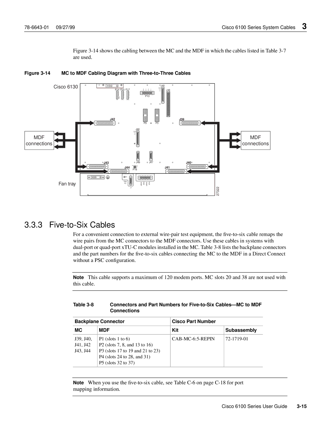
Figure 3-14 shows the cabling between the MC and the MDF in which the cables listed in Table 3-7
| are used. |
|
|
|
|
|
|
|
|
|
Figure | MC to MDF Cabling Diagram with | |||||||||
| Cisco 6130 |
|
|
|
|
|
|
| J45 |
|
|
|
|
|
|
|
|
| POOL |
| |
| P14 P15 | P17 |
| 48RTN- | 48V- B | 48RTN- 48V- A | MODEM | J48 | ||
|
| OUT | ||||||||
|
|
|
|
|
|
|
|
| A |
|
| CRIT |
| CRIT | CRIT |
|
|
|
|
|
|
| MAJ |
| MAJ | MAJ |
|
| P13 |
|
| |
| MIN | ALARM | MIN | MIN |
|
|
|
| ||
| FAN | ACO | ACO |
|
|
|
| |||
|
|
|
|
|
|
| ||||
| E2A |
| VISUAL | AUDIBLE |
|
|
|
|
|
|
| J42 |
|
|
|
|
|
|
|
| J39 |
|
|
|
|
|
| P9 |
| P3 |
| |
|
|
|
|
| J46 |
|
|
|
|
|
|
|
|
|
| MODEM |
|
|
|
|
|
|
|
|
|
| POOL |
|
|
|
|
|
|
|
|
|
| B |
|
|
|
|
|
MDF |
|
|
|
| OUT |
|
|
|
| MDF |
|
|
|
|
|
|
|
|
| ||
connections |
|
|
|
|
|
|
|
|
| connections |
| J43 |
|
|
| J49 |
|
| J47 |
| J40 |
|
|
| J44 | ANALOG TEST I/F |
|
|
|
| J41 | |
|
|
| RING |
|
|
|
| |||
|
|
|
|
| TIP |
|
|
|
|
|
|
|
|
|
| P18 |
|
|
|
|
|
|
|
|
|
| J1 |
|
|
|
|
|
|
|
|
| P2 |
|
|
|
|
|
|
| Fan tray |
| FAN | 48VA- | RTN | 48VB- | RTN |
|
| |
|
| P2 |
| 27322 | ||||||
|
|
|
|
| J1 |
|
|
|
| |
3.3.3 Five-to-Six Cables
For a convenient connection to external
Note This cable supports a maximum of 120 modem ports. MC slots 20 and 38 are not used with this cable.
Table |
| Connectors and Part Numbers for | ||
|
| Connections |
|
|
|
|
| ||
Backplane Connector | Cisco Part Number |
| ||
|
|
|
| |
MC | MDF | Kit | Subassembly | |
|
|
|
|
|
J39, J40, | P1 | (slots 1 to 6) |
| |
J41, J42 | P2 | (slots 7, 8, and 13 to 16) |
|
|
J43, J44 | P3 | (slots 17 to 19 and 21 to 23) |
|
|
| P4 | (slots 24 to 28, and 31) |
|
|
| P5 | (slots 32 to 37) |
|
|
|
|
|
|
|
Note When you use the
Cisco 6100 Series User Guide |