3 Cisco 6100 Series System Cables |
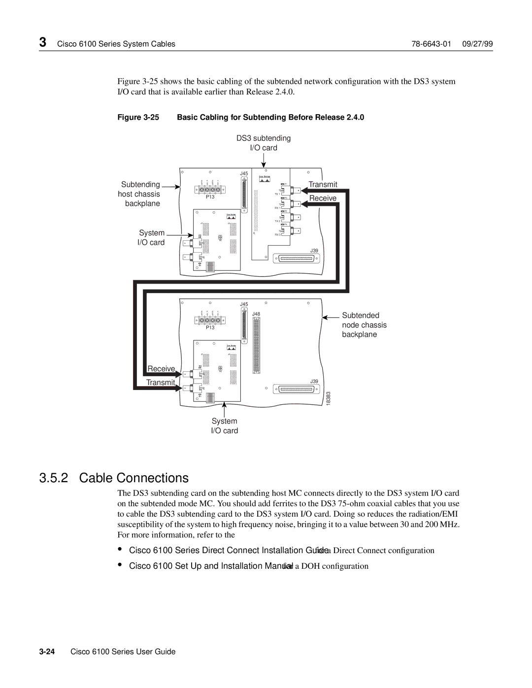
Figure 3-25 shows the basic cabling of the subtended network configuration with the DS3 system
I/O card that is available earlier than Release 2.4.0.
Figure 3-25 Basic Cabling for Subtending Before Release 2.4.0
DS3 subtending
I/O card
J45
Subtending | 48RTN | 48V B | 48RTN | 48V A |
| - | - | - | - |
host chassis |
| P13 |
| |
backplane |
|
|
|
|
| J7 | J2 |
System | P2 |
|
I/O card |
| P5 |
J4 |
| |
|
| |
| E D C B A | E D C B A |
| J3 |
|
| P1 |
|
| P1 |
| J2 |
| TX 1 |
| P3 |
| J1 |
| RX 1 |
| P2 |
| J4 |
| TX 2 |
| P4 |
J5 | J3 |
| RX 2 |
Transmit
Receive
J39
Receive
Transmit
|
|
| J45 |
|
J48 | Subtended | |||
| P13 |
| node chassis | |
|
|
|
| backplane |
J7 |
|
| J2 |
|
P2 |
|
|
|
|
|
|
| P5 |
|
| J4 |
|
|
|
| E D C B A |
| E D C B A | J39 |
| J3 |
|
| 18383 |
P1 |
|
|
| |
|
| System |
| |
|
| I/O card |
| |
3.5.2 Cable Connections
The DS3 subtending card on the subtending host MC connects directly to the DS3 system I/O card on the subtended mode MC. You should add ferrites to the DS3
•
•
Cisco 6100 Series Direct Connect Installation Guide for a Direct Connect configuration
Cisco 6100 Set Up and Installation Manual for a DOH configuration