3 Cisco 6100 Series System Cables |
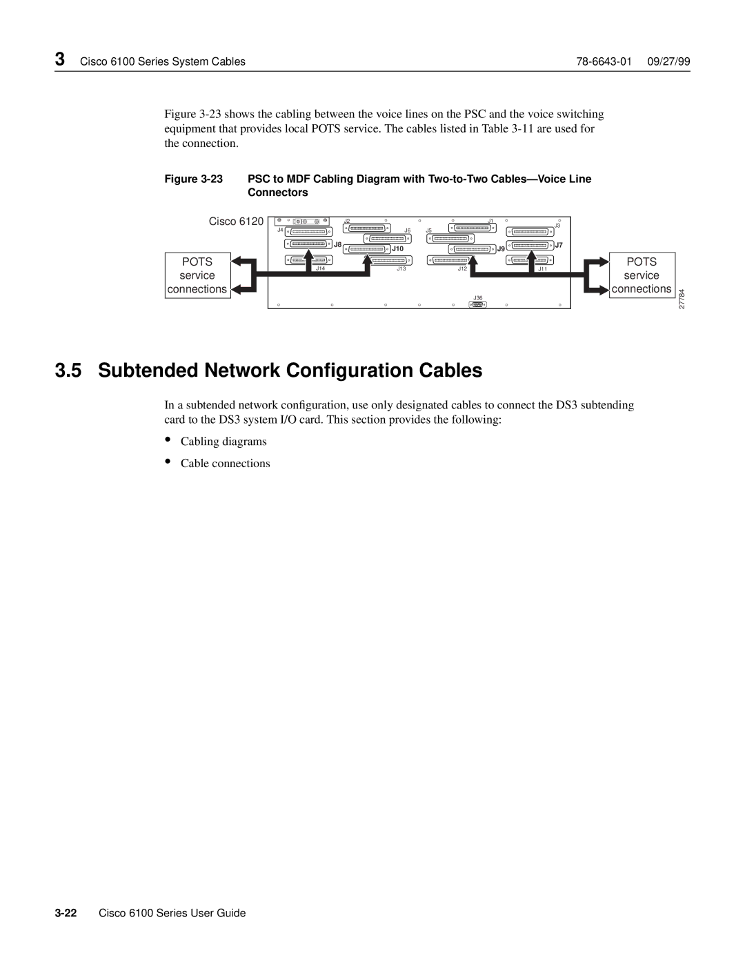
Figure 3-23 shows the cabling between the voice lines on the PSC and the voice switching equipment that provides local POTS service. The cables listed in Table 3-11 are used for the connection.
Figure 3-23 PSC to MDF Cabling Diagram with Two-to-Two Cables—Voice Line
Connectors |
|
|
|
|
|
Cisco 6120 |
| J2 |
| J1 | J3 |
J4 |
| J6 | J5 |
|
|
| J8 | J10 |
| J9 | J7 |
|
|
|
| ||
POTS |
|
|
|
| POTS |
J14 |
| J13 | J12 |
| J11 |
service |
|
|
|
| service |
connections |
|
|
| J36 | connections |
|
|
|
|
|
27784
3.5 Subtended Network Configuration Cables
In a subtended network configuration, use only designated cables to connect the DS3 subtending card to the DS3 system I/O card. This section provides the following:
•
•
Cabling diagrams
Cable connections