3 Cisco 6100 Series System Cables |
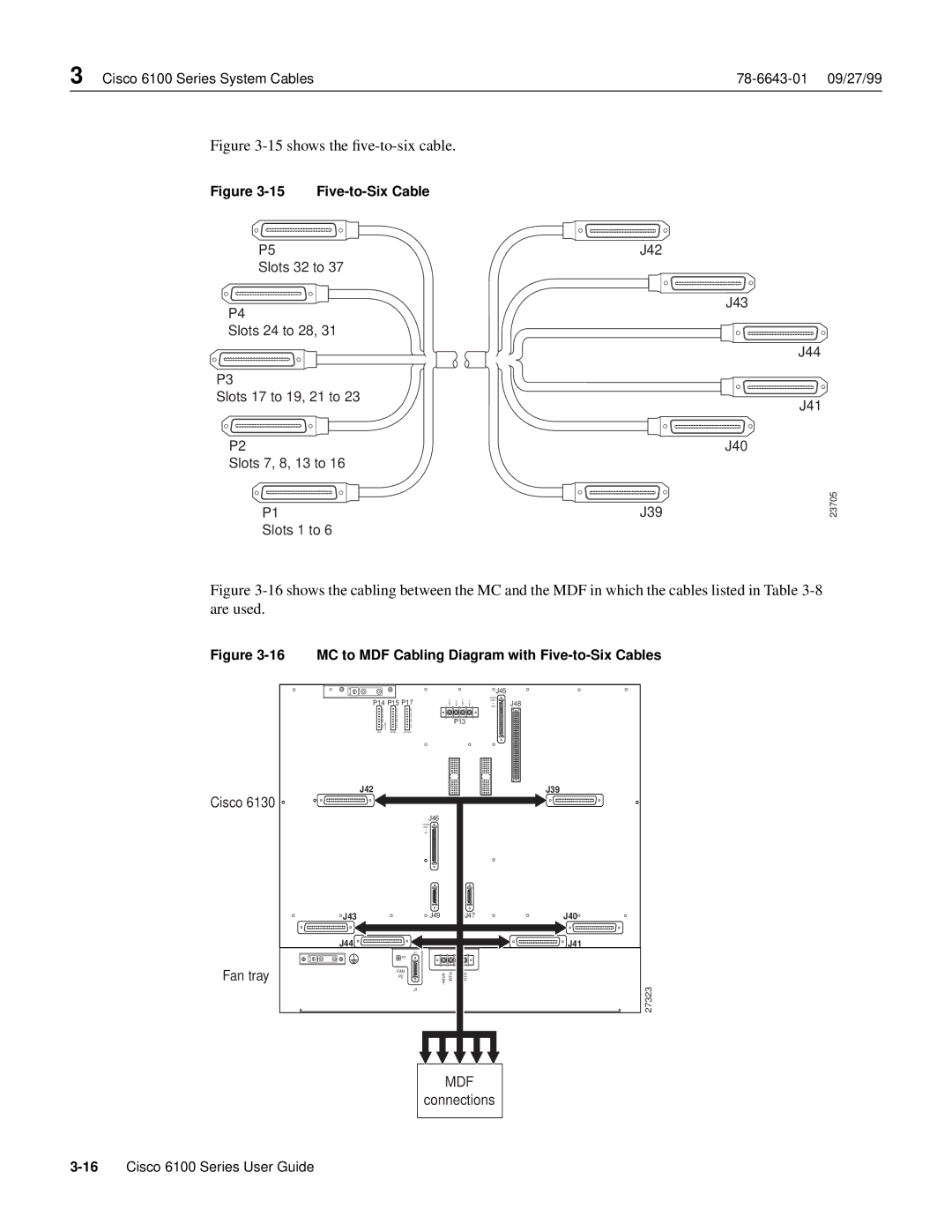
Figure 3-15 shows the five-to-six cable.
Figure 3-15 Five-to-Six Cable
P5
Slots 32 to 37
P4
Slots 24 to 28, 31
P3
Slots 17 to 19, 21 to 23
P2
Slots 7, 8, 13 to 16
P1
Slots 1 to 6
J42
J43
J44
J41
J40
J39
23705
Figure 3-16 shows the cabling between the MC and the MDF in which the cables listed in Table 3-8 are used.
Figure 3-16 MC to MDF Cabling Diagram with Five-to-Six Cables
|
|
|
|
|
|
| J45 |
|
P14 |
| P15 P17 |
|
|
| MODEM |
| |
|
| POOL | J48 | |||||
|
| A | ||||||
|
| OUT | ||||||
CRIT |
| CRIT | CRIT |
|
|
|
|
|
MAJ |
| MAJ | MAJ |
|
| P13 |
|
|
MIN | ALARM | MIN | MIN |
|
|
|
| |
FAN | ACO | ACO |
|
|
|
| ||
|
|
|
|
| ||||
E2A |
| VISUAL | AUDIBLE |
|
|
|
|
|
J42 |
|
|
|
|
|
|
| J39 |
Cisco 6130 |
|
|
|
|
|
|
|
|
|
|
|
| J46 |
|
|
|
|
|
|
|
| MODEM |
|
|
|
|
|
|
|
| POOL |
|
|
|
|
|
|
|
| B |
|
|
|
|
|
|
|
| OUT |
|
|
|
|
J43 |
|
|
| J49 |
| J47 |
| J40 |
J44 |
|
|
|
|
|
|
| J41 |
|
|
|
| J1 |
|
|
|
|
|
|
| P2 |
|
|
|
|
|
Fan tray |
| FAN | 48VA | RTN | RTN |
|
| |
|
| P2 |
|
| ||||
|
|
|
|
| ||||
|
|
|
| - |
|
|
| 27323 |
|
|
|
| J1 |
|
|
| |
|
|
|
|
|
|
|
| |
|
|
|
|
| MDF |
|
| |
|
|
|
| connections |
| |||