Cisco 6100 Series System Cables 3 |
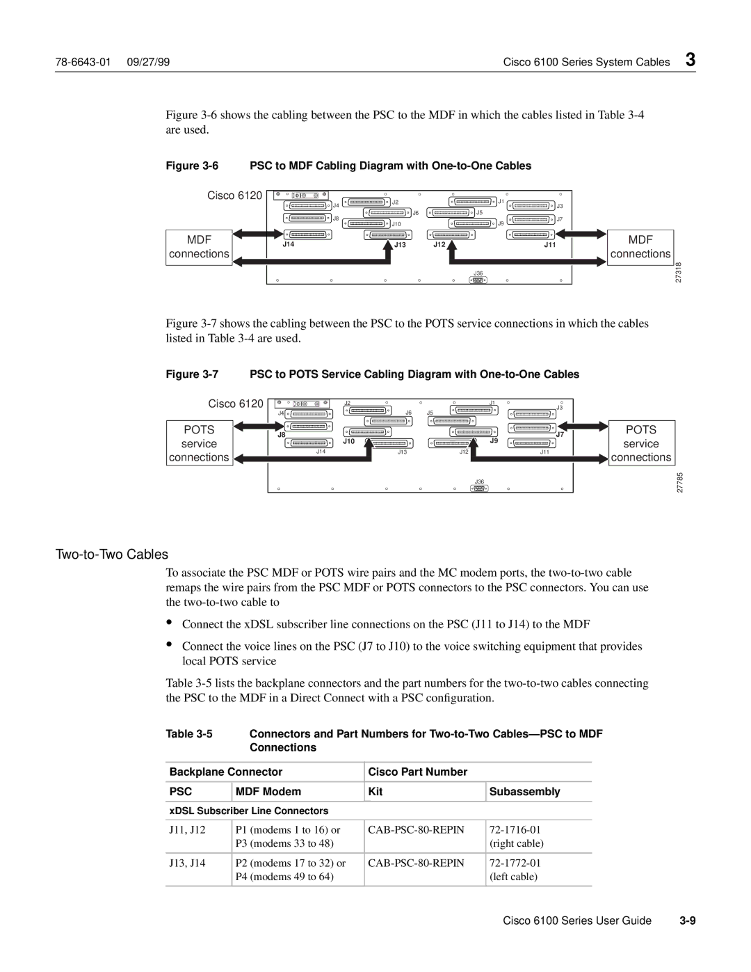
Figure 3-6 shows the cabling between the PSC to the MDF in which the cables listed in Table 3-4 are used.
Figure 3-6 PSC to MDF Cabling Diagram with One-to-One Cables
Cisco 6120 | J2 | J1 | |
J4 | |||
| J3 | ||
J8 | J6 | J5 | |
J10 | J7 | ||
| J9 |
MDF | J14 | J13 | J12 | J11 | |
connections | |||||
|
|
|
| ||
|
|
|
| J36 |
MDF
connections
27318
Figure 3-7 shows the cabling between the PSC to the POTS service connections in which the cables listed in Table 3-4 are used.
Figure 3-7 PSC to POTS Service Cabling Diagram with One-to-One Cables
Cisco 6120 | J2 |
|
| J3 | |
|
|
| J1 | ||
| J4 | J6 | J5 |
| |
POTS | J8 |
|
| J7 | |
service | J10 |
|
| J9 | |
J14 | J13 | J12 | J11 | ||
connections | |||||
|
|
|
|
J36
POTS
service
connections
27785
Two-to-Two Cables
To associate the PSC MDF or POTS wire pairs and the MC modem ports, the
•Connect the xDSL subscriber line connections on the PSC (J11 to J14) to the MDF
•Connect the voice lines on the PSC (J7 to J10) to the voice switching equipment that provides local POTS service
Table
Table |
| Connectors and Part Numbers for | |||
|
| Connections |
|
|
|
|
|
|
| ||
Backplane Connector | Cisco Part Number |
|
| ||
|
|
|
|
| |
PSC | MDF Modem | Kit | Subassembly | ||
|
|
|
|
| |
xDSL Subscriber Line Connectors |
|
|
| ||
|
|
|
|
|
|
J11, J12 | P1 | (modems 1 to 16) or |
| ||
| P3 | (modems 33 to 48) |
| (right cable) | |
|
|
|
|
|
|
J13, J14 | P2 | (modems 17 to 32) or |
| ||
| P4 | (modems 49 to 64) |
| (left cable) | |
|
|
|
|
|
|
Cisco 6100 Series User Guide |