3 Cisco 6100 Series System Cables |
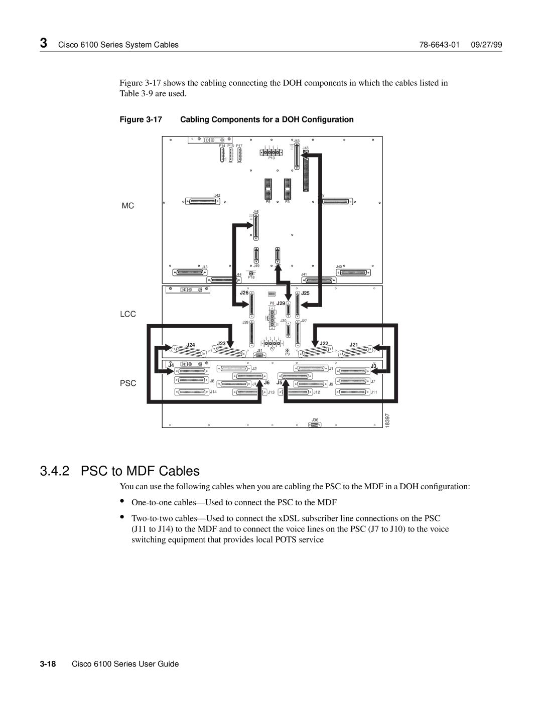
Figure 3-17 shows the cabling connecting the DOH components in which the cables listed in
Table 3-9 are used.
Figure 3-17 Cabling Components for a DOH Configuration
|
|
|
|
|
|
|
| J45 |
|
P14 |
| P15 P17 |
|
|
|
| MODEM |
| |
|
| POOL | J48 | ||||||
|
| A | |||||||
CRIT |
| CRIT | CRIT |
| OUT | ||||
|
|
|
| ||||||
MAJ |
| MAJ | MAJ |
|
|
|
|
|
|
MIN | ALARM | MIN | MIN |
|
| P13 |
|
|
|
FAN | ACO | ACO |
|
|
|
|
| ||
|
|
|
|
|
| ||||
E2A |
| VISUAL | AUDIBLE |
|
|
|
|
|
|
J42 |
|
|
|
|
|
|
|
|
|
MC |
|
|
|
|
| P9 |
| P3 |
|
|
|
| J46 |
|
|
|
|
| |
|
|
|
|
|
|
|
|
| |
|
|
|
| MODEM |
|
|
|
|
|
|
|
|
| POOL |
|
|
|
|
|
|
|
|
| B |
|
|
|
|
|
|
|
|
| OUT |
|
|
|
|
|
J43 |
|
|
| J49 |
|
| J47 |
| J40 |
|
|
|
| ANALOG TEST I/F |
|
|
|
|
|
|
|
| J44 | RING |
|
|
|
| J41 |
|
|
| TIP |
|
|
|
| ||
|
|
| P18 |
|
|
|
| ||
|
|
|
|
|
|
|
|
| |
|
|
| J26 |
|
|
|
| J25 | |
|
|
|
|
|
| P8 | J29 |
|
|
GRN JUMPER
LCC |
|
|
|
|
| |
CHASSIS | GND |
| J30 |
|
| |
|
| J27 |
| |||
| J28 |
| LOGIC |
| ||
|
| GND |
|
| ||
|
|
|
|
| ||
|
|
| ||||
J24 | J23 |
|
|
| J22 | J21 |
J31 P7
| P9 |
|
J4 | J1 | J3 |
J2 |
|
PSC | J8 | J6 J5 |
| J7 |
|
| J9 | ||
| J14 | J13 | J12 | J11 |
|
|
| J36 | 18397 |
3.4.2 PSC to MDF Cables
You can use the following cables when you are cabling the PSC to the MDF in a DOH configuration:
•
•
(J11 to J14) to the MDF and to connect the voice lines on the PSC (J7 to J10) to the voice switching equipment that provides local POTS service