3.4.2Drive Circuit for Read Motor
3 |
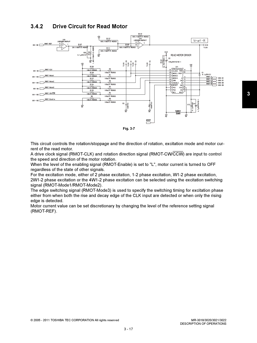
Fig. |
This circuit controls the rotation/stoppage and the direction of rotation, excitation mode and motor cur- rent of the read motor.
A drive clock signal
When the level of the enabling signal
For the excitation mode, either of 2 phase excitation,
The edge switching signal
Motor current value can be set discretionary by changing the level of the reference setting signal
© 2005 - 2011 TOSHIBA TEC CORPORATION All rights reserved | |
| DESCRIPTION OF OPERATIONS |
3 - 17