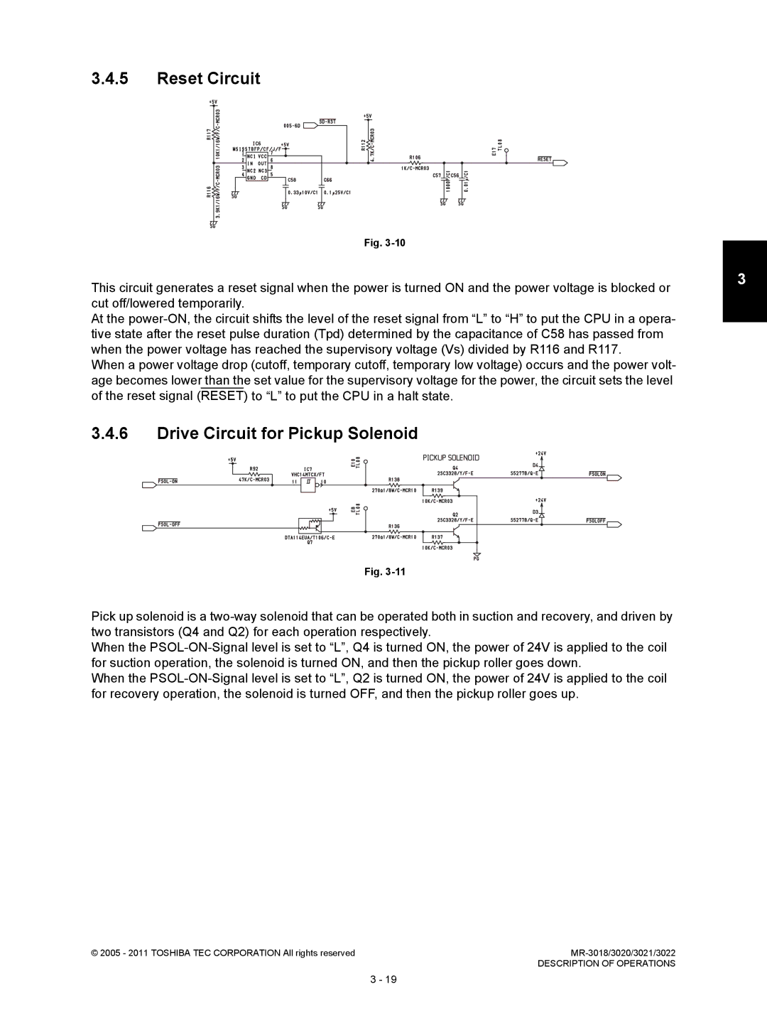
Toshiba MR-3022, MR-3018 service manual Reset Circuit, Drive Circuit for Pickup Solenoid

Models: MR-3018 MR-3022

1 122
Download 122 pages 40.04 Kb
Page 33
Image 33

3.4.5Reset Circuit

Fig. 3-10

This circuit generates a reset signal when the power is turned ON and the power voltage is blocked or cut off/lowered temporarily.

At the power-ON, the circuit shifts the level of the reset signal from “L” to “H” to put the CPU in a opera- tive state after the reset pulse duration (Tpd) determined by the capacitance of C58 has passed from when the power voltage has reached the supervisory voltage (Vs) divided by R116 and R117.

When a power voltage drop (cutoff, temporary cutoff, temporary low voltage) occurs and the power volt- age becomes lower than the set value for the supervisory voltage for the power, the circuit sets the level of the reset signal (RESET) to “L” to put the CPU in a halt state.

3.4.6Drive Circuit for Pickup Solenoid

3

Fig. 3-11

Pick up solenoid is a two-way solenoid that can be operated both in suction and recovery, and driven by two transistors (Q4 and Q2) for each operation respectively.

When the PSOL-ON-Signal level is set to “L”, Q4 is turned ON, the power of 24V is applied to the coil for suction operation, the solenoid is turned ON, and then the pickup roller goes down.

When the PSOL-ON-Signal level is set to “L”, Q2 is turned ON, the power of 24V is applied to the coil for recovery operation, the solenoid is turned OFF, and then the pickup roller goes up.

© 2005 - 2011 TOSHIBA TEC CORPORATION All rights reserved

MR-3018/3020/3021/3022


DESCRIPTION OF OPERATIONS

3 - 19

Page 33
Image 33
Toshiba MR-3022, MR-3018 service manual Reset Circuit, Drive Circuit for Pickup Solenoid