TCONT802AS32DA TOUCH SCREEN AND TCONT803AS32DA TOUCH SCREEN WITH DEHUMIDIFICATION
ADVANCED FEATURES
Outdoor or Indoor Temperature Sensor
For accuracy, the initial reading of the indoor and outdoor temperature sensors require five minutes to stabilize. See the Sensor instructions for installation information.
Special Heat Pump Features
Heat Pump with Fossil Fuel Auxiliary Heat (Dual Fuel) and Outdoor Temperature Sensor
In this operation there is no external fossil fuel kit (dual fuel kit) installed; the comfort control controls this function.
1.Choose correct heat pump application in Installer Setup Number 0170.
2.Choose Fossil Fuel Option as the backup heat source in Installer Setup Number 0200.
3.Choose No External Fossil Fuel Kit Option as controlling backup heat in installer Setup Number 0210.
4.Outdoor Temperature Sensor for Control Option is automatically chosen in Installer Setup Number 0340.
5.Choose appropriate Balance Point Temperature in Installer Setup Number 0350.
OPERATION IN HEAT MODE ABOVE BALANCE POINT (OUTDOOR TEMPERATURE)
When the outdoor temperature is above the selected Balance Point Temperature (ISU 0350), only the compressor operates and the fan (G terminal) energizes when the comfort control calls for heat.
OPERATION IN HEAT MODE BELOW BALANCE POINT (OUTDOOR TEMPERATURE)
When the outdoor temperature is below the selected Balance Point Temperature (ISU 0350), only the Fossil Fuel (auxiliary heat) operates and the fan (G terminal) does not energize when the comfort control calls for heat.
OPERATION IN EMERGENCY HEAT MODE
The balance point (outside) temperature is not used in the Emergency heat mode. When the comfort control is moved to the Emergency Heat position, the compressor is locked out. The first stage of heat is whatever is connected to the X2 terminal. The second stage of heat is what is connected to the W1 terminal. Often there is only one source of
Heat Pump with Electric Auxiliary (Backup) Heat and Outdoor Temperature Sensor
1.Choose correct heat pump application in Installer Setup Number 0170.
2.Choose Electric as Auxiliary (Backup) Heat Source in Installer Setup Number 0200.
3.Choose Outdoor Temperature Sensor for Control Option in Installer Setup Number 0340.
4.Choose Compressor Lockout Temperature in Installer Setup Number 0350.
5.Choose Auxiliary Lockout Temperature in Installer Setup Number 0360.
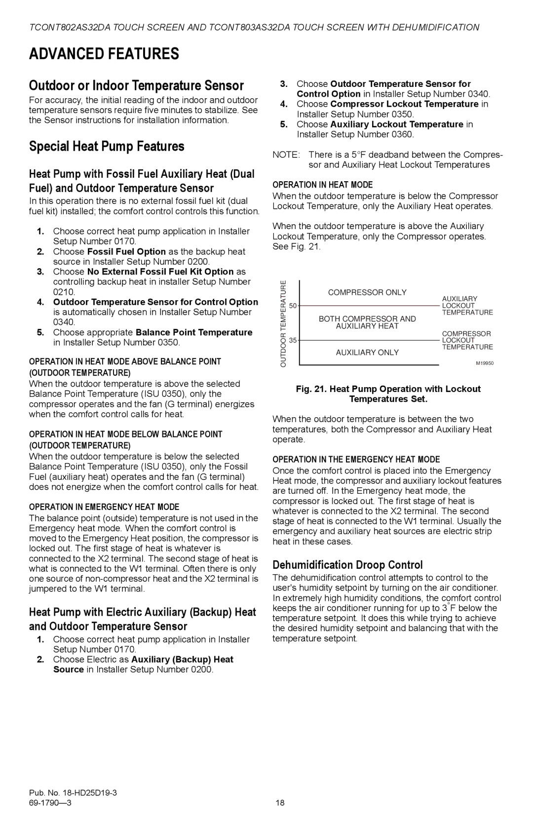
NOTE: There is a 5°F deadband between the Compres- sor and Auxiliary Heat Lockout Temperatures
OPERATION IN HEAT MODE
When the outdoor temperature is below the Compressor Lockout Temperature, only the Auxiliary Heat operates.
When the outdoor temperature is above the Auxiliary Lockout Temperature, only the Compressor operates. See Fig. 21.
TEMPERATURE |
| AUXILIARY HEAT | |
|
| COMPRESSOR ONLY | |
| 50 |
| AUXILIARY |
|
| LOCKOUT | |
|
| ||
|
|
| TEMPERATURE |
|
| BOTH COMPRESSOR AND | |
OUTDOOR |
|
| COMPRESSOR |
|
| M19950 | |
| 35 |
| LOCKOUT |
|
|
| TEMPERATURE |
|
| AUXILIARY ONLY | |
|
|
|
|
Fig. 21. Heat Pump Operation with Lockout
Temperatures Set.
When the outdoor temperature is between the two temperatures, both the Compressor and Auxiliary Heat operate.
OPERATION IN THE EMERGENCY HEAT MODE
Once the comfort control is placed into the Emergency Heat mode, the compressor and auxiliary lockout features are turned off. In the Emergency heat mode, the compressor is locked out. The first stage of heat is whatever is connected to the X2 terminal. The second stage of heat is connected to the W1 terminal. Usually the emergency and auxiliary heat sources are electric strip heat in these cases.
Dehumidification Droop Control
The dehumidification control attempts to control to the user's humidity setpoint by turning on the air conditioner. In extremely high humidity conditions, the comfort control keeps the air conditioner running for up to 3°F below the temperature setpoint. It does this while trying to achieve the desired humidity setpoint and balancing that with the temperature setpoint.
Pub. No. |
|
18 |
