CPSMC0800-100 specifications
Transition Networks CPSMC0800-100 is a versatile and robust media converter designed to enhance network connectivity in industrial environments. This device is particularly well-suited for users looking to improve the performance and reliability of their communication systems. With its ability to convert between different media types, the CPSMC0800-100 presents a myriad of applications for enterprise networks, security systems, and other critical infrastructures.One of the standout features of the CPSMC0800-100 is its support for multiple media types. It seamlessly converts Ethernet signals between copper and fiber optics, allowing for flexible integration with existing network infrastructures. This capability is essential for organizations looking to extend their network reach, especially over long distances, without compromising on signal integrity.
The CPSMC0800-100 operates at speeds of up to 1 Gbps, making it suitable for high-performance applications. This speed is complemented by its low latency, ensuring that data is transmitted quickly and reliably. This is particularly important in environments where real-time data transmission is crucial, such as surveillance systems and industrial control networks.
Another key characteristic of this media converter is its robust design, optimized for harsh environmental conditions. With an extended temperature range, the CPSMC0800-100 can operate in temperatures ranging from -40°C to 75°C. This durability ensures that the device can function effectively in various settings, including factories, outdoor installations, and remote locations.
The CPSMC0800-100 is also equipped with advanced features such as IEEE 802.3az Energy Efficient Ethernet support. This technology helps lower power consumption, which is a significant consideration for organizations looking to reduce operational costs while maintaining network performance. Additionally, it has built-in LEDs for monitoring link activity and power status, enabling easy troubleshooting and maintenance.
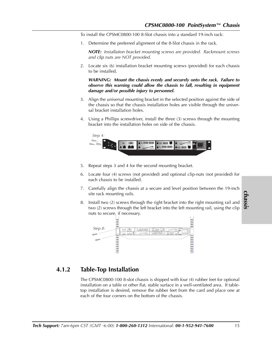
Installation and configuration of the CPSMC0800-100 are made simple through its compact design and plug-and-play functionality. The device can be easily mounted in various locations, ensuring that deployment is quick and hassle-free. Overall, Transition Networks' CPSMC0800-100 media converter stands out as a reliable and effective solution for organizations aiming to enhance their network infrastructure with flexibility, speed, and durability. Whether for expanding existing networks or adapting to new technologies, this media converter is a valuable asset in modern communications.

